Sign In
Upload
Manuals
Brands
Carrier Manuals
Industrial Equipment
PrimeLINE
Carrier PrimeLINE Manuals
Manuals and User Guides for Carrier PrimeLINE. We have
1
Carrier PrimeLINE manual available for free PDF download: Operation And Service Manual
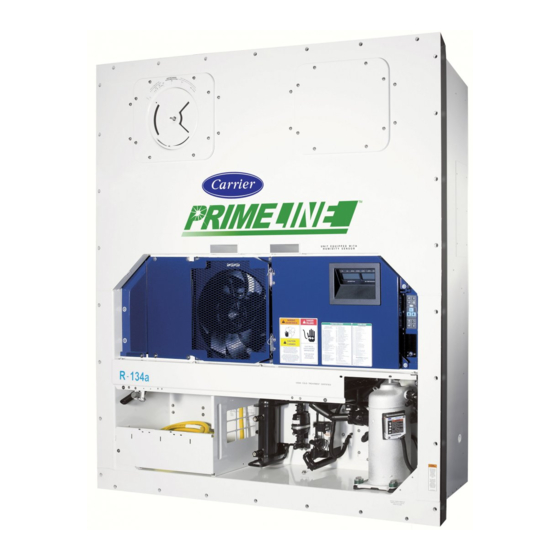
Carrier PrimeLINE Operation And Service Manual (198 pages)
Container Refrigeration Units
Brand:
Carrier
| Category:
Industrial Equipment
| Size: 9.16 MB
Table of Contents
Table of Contents
4
Description
23
3.1 General Description
23
Refrigeration Unit - Front Section
23
Figure 3.1 Refrigeration Unit - Front Section
23
Compressor Section
24
Air-Cooled Condenser Section
24
Figure 3.2 Compressor Section
24
Figure 3.3 Condenser Section with "C" Shape Coil (Pids < NT3000)
25
Figure 3.4 Condenser Section, with MCHE and Steel Receiver (Pids NT3000 to NT3099)
26
Figure 3.5 Condenser Section, with MCHE and Aluminum Receiver (Pids > NT3100)
27
Water-Cooled Condenser Section
28
Figure 3.6 Tube in Shell Water-Cooled Condenser
28
Fresh Air Makeup Vent
29
Evaporator Section
29
Figure 3.7 Brazed Plate Water-Cooled Condenser
29
Figure 3.8 Evaporator Section
30
Figure 3.9 Evaporator Section - Primeline ONE
31
Control Box Section
32
Communications Interface Module
32
Figure 3.10 Control Box Section
32
3.2 Refrigeration System Data
33
Table 3-1 Refrigeration System Data
33
3.3 Electrical Data
34
Table 3-2 Electrical Data
34
3.4 Safety and Protective Devices
35
Electronic Expansion Valve (EEV)
35
Table 3-3 Safety and Protective Devices
35
Figure 3.11 Refrigeration Circuit Schematic - Standard Operation
37
Figure 3.12 Refrigeration Circuit Schematic - Economized Operation
38
Figure 3.13 Refrigeration Circuit Schematic - Water-Cooled Condenser (Tube in Shell)
39
Figure 3.14 Refrigeration Circuit Schematic - Water-Cooled Condenser (Brazed Plate)
40
Microprocessor
41
4.1 Temperature Control Microprocessor System
41
Controller
41
Display Module and Keypad
41
Figure 4.1 Controller
41
Figure 4.2 Display Module and Keypad
41
Table 4-1 Display Module Leds
42
Table 4-2 Keypad Function
42
4.2 Controller Software
43
Configuration Software (Cnf Variables)
43
Table 4-3 Controller Configuration Variables
43
Operational Software (CD Function Codes)
44
Table 4-4 Controller Function Codes
45
4.3 Modes of Operation
59
Start up - Compressor Phase Sequence
59
Start up - Compressor Bump Start
59
Perishable Mode Temperature Control
59
Perishable Pulldown
59
Perishable Steady State
59
Perishable Idle, Air Circulation
59
Perishable Heating
60
Perishable Dehumidification
60
Figure 4.3 Controller Operation - Perishable Mode
60
Perishable Dehumidification - Bulb Mode
61
Perishable Economy
61
Perishable Mode Cooling - Sequence of Operation
62
Figure 4.4 Perishable Mode Cooling
62
Perishable Mode Heating - Sequence of Operation
63
Perishable Mode - Trim Heat
63
Frozen Mode - Temperature Control
63
Frozen Steady State
63
Figure 4.5 Perishable Mode Heating
63
Frozen Idle Mode
64
Frozen "Heat" Mode
64
Frozen Economy Mode
64
Frozen Mode Cooling - Sequence of Operation
64
Figure 4.6 Controller Operation - Frozen Mode
64
Defrost
65
Figure 4.7 Frozen Mode
65
Defrost Operation
66
Defrost Related Settings
67
Figure 4.8 Defrost
67
Protection Modes of Operation
68
QUEST Mode
68
4.4 Controller Alarms
69
Table 4-5 Alarm Indications and Descriptions
70
4.5 Pre-Trip Diagnostics
82
Controller Pre-Trip Test Codes
82
Table 4-6 Controller Pre-Trip Test Codes
82
4.6 Datacorder
88
Datacorder Description
88
Datacorder Configuration Software
89
Table 4-7 Datacorder Configuration Variables
89
Table 4-8 Sensor Configuration
90
Datacorder Operational Software
91
Table 4-9 Datacorder Function Code Assignments
92
Datacorder Power up
93
Datacorder Alarms
93
Table 4-10 Datacorder Alarm Indications
94
Pre-Trip Data Recording
95
Table 4-11 Datacorder Pre-Trip Result Records
95
Datacorder Communications
96
USDA Cold Treatment
97
Figure 4.9 Datacorder Configuration Screen
97
Figure 4.10 Datacorder Probe Calibration Screen
98
ISO Trip Header
99
Figure 4.11 Datacorder Probe Calibration Screen
99
Figure 4.12 Datacorder Systems Tool Screen
99
Operation
101
5.1 Inspection
101
5.2 Connect Power
101
Connecting to 380/460 VAC Power
101
Connecting to 190/230 VAC Power
101
5.3 Adjust Fresh Air Makeup Vent
102
Upper Fresh Air Makeup Vent
102
Figure 5.1 Autotransformer
102
Lower Fresh Air Makeup Vent
103
Figure 5.2 Upper Fresh Air Make up Flow Chart
103
Vent Position Sensor
104
5.4 Connect Water-Cooled Condenser
104
Water-Cooled Condenser with Water Pressure Switch
104
Water-Cooled Condenser with Condenser Fan Switch
104
5.5 Connect Remote Monitoring Receptacle
105
5.6 Starting and Stopping Instructions
105
Starting the Unit
105
Stopping the Unit
105
5.7 Start-Up Inspection
105
Physical Inspection
105
Check Controller Function Codes
105
Start Temperature Recorder
105
Complete Inspection
105
5.8 Pre-Trip Diagnosis
106
Prior to Starting a Pre-Trip
106
Starting a Pre-Trip
106
Displaying Pre-Trip Test Results
107
5.9 Probe Diagnostics
107
5.10 Optional Operating Modes
108
Emergency Bypass Operation
108
Tripwise
109
Figure 5.3 Diagram of Emergency Bypass Connections
109
Figure 5.4 Tripwise Status in Datacorder
110
Xtendfresh
111
Figure 5.5 Generating Tripwise Summary Report
111
Automatic Cold Treatment Mode
112
Automatic Setpoint Change Mode
113
Quest Mode
114
Fuelwise Mode
114
Figure 6.1 Unit Troubleshooting Sequence
115
Microprocessor Malfunction
119
6.10 no Evaporator Air Flow or Restricted Air Flow
119
6.11 Xtendfresh Not Operating
119
6.12 Electronic Expansion Valve Malfunction
119
6.13 Autotransformer Malfunction
120
6.14 Water-Cooled Condenser or Water Pressure Switch
120
Compressor Operating in Reverse
120
Abnormal Temperatures
120
Abnormal Currents
120
Service
121
Section Layout
121
Manifold Gauge Set
121
Figure 7.1 Manifold Gauge Set
121
Evacuating the Manifold Gauge Set
122
Service Connections
122
Figure 7.2 Manifold Gauge / Hose Set
122
Connecting the Manifold Gauge Set
123
Removing the Manifold Gauge Set
123
Pump down the Unit
123
Figure 7.3 Service Valve
123
Automatic Pump down
124
Manual Pump down
124
Refrigerant Leak Checking
124
Evacuation and Dehydration
125
General
125
Preparation
125
Evacuate and Dehydrate - Complete System
125
Figure 7.4 Refrigeration System Service Connections
125
Evacuate and Dehydrate - Partial System
126
Checking the Refrigerant Charge
126
Adding Refrigerant to System - Full Charge
127
Adding Refrigerant to System - Partial Charge
127
Converting to R-513A Refrigerant
127
Compressor
128
Removing and Replacing the Compressor
128
Figure 7.5 Compressor Kit
129
7.10 High Pressure Switch
130
Checking High Pressure Switch
130
Figure 7.6 High Pressure Switch Testing
130
Replacing High Pressure Switch
131
7.11 Condenser Coil
131
Condenser Coil Cleaning
131
Condenser Coil Removal
131
Condenser Coil Preparation
132
Figure 7.7 Condenser Fan Position
133
Figure 7.8 Water-Cooled Condenser Cleaning - Forced Circulation
139
Figure 7.9 Water-Cooled Condenser Cleaning - Gravity Circulation
140
Figure 7.10 Heater Arrangement
141
Figure 7.11 Evaporator Fan Assembly
144
Figure 7.12 Access Panel Torque Pattern
145
Figure 7.13 Electronic Expansion Valve (EEV)
146
Figure 7.14 Coil View of Economizer Solenoid Valve (ESV)
149
Figure 7.15 Economizer Expansion Valve
150
Figure 7.16 Adapter and O-Ring
151
Figure 7.17 View of Digital Unloader Valve (DUV) Assembly
152
Table 7-1 Valve Override Control Displays
153
Figure 7.18 Autotransformer
154
Figure 7.19 Controller
155
Table 7-2 Test Point Descriptions
155
Table 7-3 Sensor Resistance - AMBS, DTS, ETS, RRS, RTS, SRS, STS
162
Table 7-4 Sensor Resistance - Primeline CPDS
163
Figure 7.20 Supply Sensors - Cover Assembly and Sensors
164
Figure 7.21 Removing Front Access Panels
165
Figure 7.22 Removing Evaporator Motor
165
Figure 7.23 Return Sensors - Bracket
165
Figure 7.24 Return Sensors - Cutting Wire Ties
166
Figure 7.25 Dataline - Probe Calibration
166
Figure 7.26 Dataline - Calibrate Sensors Button
167
Figure 7.27 Dataline - Enter Service Center Information
167
Figure 7.28 Ice Bath
168
Figure 7.29 Dataline - Start Cal Button
168
Figure 7.30 Dataline - Calibration Results
169
Figure 7.31 Sensor Types
170
Figure 7.32 Sensor and Cable Splice
170
Figure 7.33 STS/SRS Positioning
171
Figure 7.34 RRS/RTS Positioning
171
Figure 7.35 ETS1/ETS2 Positioning
172
Figure 7.36 Compressor Discharge Temperature Sensor
172
Figure 7.37 Communications Interface Installation
174
Table 7-5 R-134A Refrigerant Pressure Temperature Chart
175
Table 7-6 R-513A Refrigerant Pressure Temperature Chart
178
Table 7-7 Recommended Bolt Torque Values (Dry, Non-Lubricated for 18-8 Stainless Steel)
181
Figure 8.1 LEGEND - Standard Unit Configuration
183
Figure 8.2 Schematic Diagram
184
Figure 8.3 Unit Wiring Diagram (Sheet 1 of 2)
185
Figure 8.4 Unit Wiring Diagram (Sheet 2 of 2)
186
Figure 8.5 Legend - Unit with Auto Transformer
187
Figure 8.6 Schematic Diagram - Unit with Auto Transformer
188
Figure 8.7 Unit Wiring Diagram - Unit with Auto Transformer (Sheet 1 of 2)
189
Figure 8.8 Unit Wiring Diagram - Unit with Auto Transformer (Sheet 2 of 2)
190
Advertisement
Advertisement
Related Products
Carrier Programmable Dual Fuel Thermostats
Carrier Programmable Thermostats
Carrier PROGRAMMABLE THERMOSTAT
Carrier PRO-DIALOG
Carrier PremierLink 50TFQ004 Series
Carrier PremierLink 50TFQ005 Series
Carrier PremierLink 50TFQ006 Series
Carrier PremierLink 50TFQ007 Series
Carrier PremierLink 50TFQ009 Series
Carrier PremierLink 50TFQ012 Series
Carrier Categories
Air Conditioner
Heat Pump
Furnace
Thermostat
Chiller
More Carrier Manuals
Login
Sign In
OR
Sign in with Facebook
Sign in with Google
Upload manual
Upload from disk
Upload from URL