Burkert Type 2000 Manuals
Manuals and User Guides for Burkert Type 2000. We have 14 Burkert Type 2000 manuals available for free PDF download: Operating Instructions Manual, Assembly Instructions Manual, Quick Start Manual, Service Manual
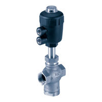
Bürkert Type 2000 Operating Instructions Manual (94 pages)
2/2-Way Angle Seat Valve, 3/2-Way Globe Valve
Brand: Bürkert
|
Category: Control Unit
|
Size: 5 MB
Table of Contents
Advertisement

Burkert Type 2000 Operating Instructions Manual (87 pages)
2/2-Way Angle Seat Valve, 3/2-Way Globe Valve
Brand: Burkert
|
Category: Control Unit
|
Size: 1 MB
Table of Contents
Burkert Type 2000 Assembly Instructions Manual (88 pages)
Stroke limitation / Min-, max. stroke limitation
Hand wheel / Electrical position repeater
Brand: Burkert
|
Category: Control Unit
|
Size: 3 MB
Table of Contents
Advertisement
Burkert Type 2000 Assembly Instructions Manual (64 pages)
Stroke limitation, Min./max. stroke limitation, Hand wheel, Electrical position feedback
Brand: Burkert
|
Category: Controller
|
Size: 1 MB
Table of Contents

Burkert Type 2000 Quick Start Manual (56 pages)
2/2-Way angle seat valve
Brand: Burkert
|
Category: Control Unit
|
Size: 3 MB
Table of Contents

Bürkert Type 2000 Operating Instructions Manual (28 pages)
2/2-way valve, manually actuated
Brand: Bürkert
|
Category: Control Unit
|
Size: 1 MB
Table of Contents

Burkert Type 2000 Operating Instructions Manual (44 pages)
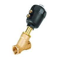
CLASSIC 2/2-way angle seat valve
Brand: Burkert
|
Category: Control Unit
|
Size: 2 MB
Table of Contents

Burkert Type 2000 Operating Instructions Manual (38 pages)
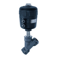
2/2-way angle seat valve
Brand: Burkert
|
Category: Control Unit
|
Size: 2 MB
Table of Contents

Burkert Type 2000 Operating Instructions Manual (37 pages)
2/2-way angle seat valve
Brand: Burkert
|
Category: Control Unit
|
Size: 2 MB
Table of Contents

Bürkert Type 2000 Service Manual (41 pages)
Replacement of valve and seal set Conversion of control function
Brand: Bürkert
|
Category: Control Unit
|
Size: 2 MB
Table of Contents
Burkert Type 2000 Operating Instructions Manual (39 pages)
2/2-way angle seat valve
Brand: Burkert
|
Category: Control Unit
|
Size: 2 MB
Table of Contents

Bürkert Type 2000 Operating Instructions Manual (29 pages)
2/2 way angle seat valve, 3/2 way globe valve
Brand: Bürkert
|
Category: Control Unit
|
Size: 1 MB
Table of Contents

Burkert Type 2000 Quick Start Manual (31 pages)
2/2-Way Angle Seat Valve
Brand: Burkert
|
Category: Control Unit
|
Size: 1 MB
Table of Contents

Burkert Type 2000 Operating Instructions Manual (24 pages)
2/2-Way Angle-Seat Valve
3/2-Way Globe Valve
Brand: Burkert
|
Category: Control Unit
|
Size: 0 MB