Sign In
Upload
Manuals
Brands
BST Manuals
Controller
ekr CON 100
BST ekr CON 100 Manuals
Manuals and User Guides for BST ekr CON 100. We have
1
BST ekr CON 100 manual available for free PDF download: Installation And Operating Manual
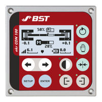
BST ekr CON 100 Installation And Operating Manual (130 pages)
Brand:
BST
| Category:
Controller
| Size: 4.36 MB
Table of Contents
Table of Contents
3
About this Document
7
What You Need to Know
7
Target Group
7
Storage and Distribution
7
Meanings of the Safety Instructions and Symbols
7
Safety Instructions
7
Symbols
8
Operation Using Keys
8
More Detailed Information
8
About Safety
9
Intended Use
9
Non-Intended Use
9
Non-Intended Infringement of Guidelines
10
Non-Intended Operation
10
Non-Intended Modification of Electronic Data
10
Safety Instructions
11
General Safety Instructions
11
Qualification of the Personnel
13
Duties of the Operating Company and Personnel
14
Duties of the Operating Company
14
Duties of the Personnel
15
Conduct in the Event of Danger and Accidents
15
Personal Protective Equipment
16
Guarantee and Liability
16
Disclaimer
16
Exceptions to the Disclaimer
17
License and Liability for Software Supplied
17
Design and Function
18
Design
18
Function
19
Guiding Modes
19
Control and Display Elements
20
Graphic Display
20
Keys
20
Message Output "System OK
21
Connectable Components
22
Designation of the Sensors
23
Edge Sensors (Sensor 1/2)
23
Line and Contrast Sensor (Sensor 3)
24
Accessories
24
Name Plate
25
Technical Specifications
26
Controller
26
Ambient Conditions
26
Protection Category
26
Power Supply
26
Analogue Inputs
27
Digital Inputs
27
Output Motor Output Stage
27
Message Output "System OK
28
Interfaces
28
Display
29
Weight and Dimensions
29
Power Pack
30
Sensors
31
Edge Sensors
31
Line and Contrast Sensor CLS Pro 600
33
Electric Motor Powered Actuators
34
Emissions
35
Rohs Conformity
35
Transport, Delivery and Storage
36
Transport
36
Scope of Delivery
37
Unpacking the Delivery
37
Storage
37
Installation
38
Safety Instructions
38
Selecting the Installation Location
39
Installing the Controller
40
Installation Cut-Out
40
Space Requirement for the Connecting Cable
40
Electrical Connection
42
Safety Instructions
42
Cable Routing
43
Connecting the Cables
44
Ensuring Equipotential Bonding
45
Connections on the Controller
46
Sockets / Plugs
47
Overview
47
X100 - Power Supply
48
X101, X102 - CAN-Bus
49
X103 - Actuator
50
X104 - Network
51
X105 - Service
52
Terminal Strips
53
Overview
53
X1 - Digital Inputs
54
X2 - Position Feedback Actuator
55
X3 - Servo Center Transducer
56
X4 - Brushless Motor / DC
57
X5 - Message Output "System OK
58
Service Indications
59
Service Leds Overview
59
Display of Device Status
59
Display of Bus Status
59
Status Display of Power Supply
60
Status Display of Message Output "System OK
60
Commissioning
61
Safety Instructions
61
Requirements
62
Setting the DIL Switches
62
Using the DIL Switch
63
Setting the DIL Switches
64
Setting the Motor Rotation Direction
65
Commissioning the Actuator Without Position Feedback
66
Set the Guiding Direction for Center Positioning
66
Setting the Gain of the Servo Center Transducer
67
Commissioning the Actuator with Position Feedback
68
Set the Guiding Direction for Center Positioning
68
Setting Stroke Limitation and Servo-Center Position
69
Performing the Material Setup
72
Adjusting the Controller Gain
72
Operation
74
Safety Instructions
74
Control Panel
74
Operation Display
76
Overview
76
Operation Display Edge Sensors (Sensor 1/2)
77
Operation Display Line and Contrast Sensor (Sensor 3)
78
Actuator Operation Display
80
Special Displays
81
Limit Switch Active
81
Actuator Blocked (Motor Overcurrent)
81
Impermissible Supply Voltage
82
Motor Control Timeout
82
Controller Interlock Active
83
Actuator Bus Connection Fault
83
Loss of the Line / Contrast Transition
84
External Motor Output Stage Fault (Drive Module 160)
84
Performing the Material Setup
85
Overview
85
Activating the Material Setup
87
Cancelling Material Setup
87
Procedure for Web Edge Guiding
88
Procedure for Web Center-Line Guiding
90
Selecting the Operating Mode for the IR 2011/40 Edge Sensor
93
Function
93
Requirements
93
IR 2011/40 Operating Modes
93
Operating Mode Selection
95
Selecting the Guiding Mode
96
Selecting the Operating Mode
97
Manual Mode
97
Automatic
97
Center Positioning
98
Watchdog
99
Setting the Guiding Setpoint
102
Optimizing the Controller Gain
104
Calling up the Setup Menu
106
Displaying System Information
108
Displaying System Components
109
Displaying the DIL Switch Settings
110
Displaying the Status of the Digital Inputs
112
Displaying the CAN-Bus Status
113
Restoring Factory Default Settings
114
Remote Control (Digital Inputs)
115
Safety Information
115
Digital Inputs
115
Truth Table
116
Maintenance and Cleaning
117
Safety Instructions
117
Maintenance Table
118
Maintenance and Cleaning Work
118
Cleaning the Controller Housing
118
Cleaning the Edge Sensor Housing
118
Cleaning the Housing of the CLS Pro 600 Line and Contrast Sensor
119
Cleaning the Electric Motor Powered Actuator Housing
119
Troubleshooting
120
Accessories and Spare Parts
124
Order Address
124
Accessories
124
Customer Services
125
Shutting down and Disposal
126
Index
127
Advertisement
Advertisement
Related Products
BST ekr CON 600
BST ekr CON 600 net
BST ekr 500
BST ekr 500 Plus
BST ekrPro Com60
BST CDU-200R
BST CCD CAM 100
BST CLS CAM 100
BST EKR 1500PDP
BST ECOGuide MD.464.EN.05
BST Categories
Speakers
Speaker System
Amplifier
Controller
Security Sensors
More BST Manuals
Login
Sign In
OR
Sign in with Facebook
Sign in with Google
Upload manual
Upload from disk
Upload from URL