Sign In
Upload
Manuals
Brands
Bernina Manuals
Sewing Machine
B 590
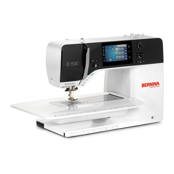
Bernina B 590 Manuals
Manuals and User Guides for Bernina B 590. We have
3
Bernina B 590 manuals available for free PDF download: Service And Maintenance Manual
Bernina B 590 Service And Maintenance Manual (187 pages)
Embroidery Module
Brand:
Bernina
| Category:
Sewing Machine
| Size: 9 MB
Table of Contents
Table of Contents
2
Chapter 1 - General Information
6
Safety Regulations
6
Warning: Dangerous Voltage Levels
7
ESD-Related Note: Electrostatic Discharge (ESD)
8
Tools and Gauges
9
Handling Adjustments
12
Abbreviations/Names Used
12
Cleaning
13
Technical Specifications of 4 & 5 Series
14
Chapter 2 - Electronics and Wiring
17
BERNINA B 590 (BERNINA Series 4 & 5) Block Diagram
17
PCBA-Power
18
PCBA-CPU-Module (ARM9) General Information
19
PCBA-CPU-Module/Arm9
19
PCBA-Base General Information
20
PCBA-Base with Feed-Dog Drop Detection
20
PCBA-Position Hall
21
PCBA-Threader
21
PCBA-Cover Including Display and Touch Screen
22
Pcba
22
PCBA-Stitching Head (PCBA-RET)
23
PCBA-Lower-Thread Observer (LTO)
24
ABC Sensor Support (Presser-Foot Recognition)
24
PCBA Embroidery Module Detection
25
Handling of Electronic Components
26
Returning Defective Electronic Components
26
Repairs of Electronic Components (Pcba's)
26
Chapter 3 - Troubleshooting
27
General Troubleshooting Flow Chart
27
Operating Voltage Functional Test
28
Use and Functions of Leds
28
Upper-Thread Sensor
30
Lower-Thread Sensor
31
Touch Screen Calibration
32
EEPROM Missing or Misprogrammed
32
Machine Doesn't Start after Repair
32
Update Failed
33
Sewing-Off Guidelines
35
Personal Notes Regarding Troubleshooting
39
Chapter 4 - Removal and Refitting of Components
40
Covers
40
Service Cover See ESD-Related Note
40
Front Cover
41
Rear Cover
44
Freearm Cover
45
Base-Plate Cover
46
Electronics, Sensors, Switches, Magnets
47
PCBA-Power Including PCB Housing
47
PCBA-CPU-Module (ARM9) General Information
49
PCBA-CPU-Module (ARM9)
50
PCBA-Base - with Feed-Dog Drop Detection
51
EEPROM (Electrically Erasable Programmable Read-Only Memory)
51
PCBA-Position Hall
52
PCBA-Threader
53
PCBA-Front Cover Including Display and Touchscreen
54
PCBA-Head
55
PCBA-Lower Thread Sensor
56
Sensor Support ABC (Presser Foot Recognition)
57
Head Frame and Frame Arm LED Sewing Light
58
PCBA-Embroidery Module Detection
60
Electromechancial/Mechanical Components
61
Hook and Hook Driver
61
Main Feed-Dog
64
Replacing the Hook Driver Belt
65
Stitch Plate Carrier with Integrated Thread-Cutting Unit
66
Replacing the Knife of Integrated Thread-Cutter Unit
68
Base Shaft
70
Crank Shaft and Stitch Length Stepping Motor
71
Replacing Base Shaft and Upper Shaft Connecting Belt
72
Feed-Dog Carrier and Advance Link
73
Upper Feed Crank
74
Upper Feed (Dual Feed)
74
Clutch Carriage
75
Upper-Thread Tension Unit with Thread Take-Up Cover
77
Toothed Rack, Machines with Stepper Motor Presser Foot Pressure
78
Toothed Rack, Machines with Manual Presser Foot Pressure
80
Presser Foot Bar
81
Assembly Unit BERNINA Dual Feed BDF
82
Needle-Bar Support
84
Needle Bar
85
Needle Clamp
86
Threading Mechanism
87
Thread Tension
89
Thread Take-Up Lever and Thread Regulator Spring
90
Thread Regulator Spring
91
Main Motor
91
Presser-Foot Pressure Stepping Motor
92
Stitch-Width Stepping Motor
93
Winder Unit
94
Chapter 5 - Adjustments
95
Belt Tensions
95
Vertical Shaft-/Base Shaft Belt Tension
95
Drive Motor Belt Tension
96
Hook Drive Belt Tension
97
Head-Frame Plate Position (Rough Setting)
98
Position of Head-Frame Plate/Stitch Plate in Y-Direction
98
Position of Head-Frame Plate/Stitch Plate in X-Direction
99
Presser-Foot Adjustment
100
Darning Foot Height
100
Presser-Foot Fixation
101
Needle Settings
102
Distance between Needle Bar and Presser-Foot Bar
102
Needle Distribution
103
Zigzag Stitch Width Limiter
104
Hook, Needle Drive and Feed-Dog Movement Timing
105
Feed-Dog Lift Movement (Base Shaft and Main Shaft Timing)
105
Base Shaft-/Load Lock Screw Distance
106
Loop Lift
107
Needle- / Hook Distance
109
Needle Penetration in y Directions
109
Needle Height
110
Needle Height Without Basting Device
111
Feed Dog Settings
112
Main Feed-Dog Horizontal Position
112
Main Feed-Dog Height 0.9-1. 0 MM
112
Main Feed Mechanical Balance - Basic Setting
114
Upper Feed (Dual Feed)-/Main Feed Synchronization (Pinning Position)
115
Upper Feed-Dog (Dual Feed) Mechanical Balance - Basic Setting
116
Fine-Adjustment
116
Clutch Carriage/Thread Cutter
117
Clutch Carriage Solenoid Adjustment
117
Clutch Carriage Alignment
118
Clutch Carriage Timing
119
Thread Cutter
120
Thread Guide Plate
120
Hall Position Synchronization
121
Threader
122
Basting Device (B 590)
123
Needle Bar Guide
123
Time of Clutch Release
124
Thread Regulator
125
Thread Tension
126
Upper Thread Tension
126
Lower-Thread Tension (Basic Setting)
127
Winder
128
Lower-Thread Sensor Position
129
Chapter 6 - Service Program
130
Starting the Test Program
130
Section 1 - Service Information
132
Machine Basic Data
132
Machine Firmware Data and Technical Information
132
Machine Operating Hours Data
133
Stitch Counter Data
133
BSR (BERNINA Stitch Regulator) Data
133
Machine Servicing Data
134
Saving Customer Data
134
Customer Related Data (Customer Information)
135
Dealer Related Data (Dealer Information)
135
Log File
136
Section 2 - Screen, Symbols
136
Touch Screen Calibration
136
LCD (Screen Brightness)
137
Blank Dark LC Display (Screen)
137
Blank White LC Display (Screen)
137
RGB (Red, Green and Blue) Screen
138
Keyboard Lights
138
LED Sewing Light and Brightness
139
Section 3 - Location of Sensors in the Machine
139
Threader Sensor
139
Presser-Foot Micro Switch
140
Lower-Thread Sensor
140
Feed-Dog Drop
141
Bobbin Winder Micro-Switch
142
Frei Hand System FHS
142
Section 4 - Signalse
143
Stitch Width and Stitch Length Knobs
143
Functions of Keys and Buttons on Machine
144
Start-/Stop Slide (SSU)
144
Foot Control
145
Upper Thread Observer (UTO)
145
BERNINA Stitch Regulator (BSR)
146
PCBA-Position
146
Speaker
147
USB Ports
147
Basting Solenoid
148
Presser-Foot Recognition
148
BSR Foot Interface
149
Section 5 - Locations of Stepping Motors in the Machine
150
Stitch-Width Stepping Motor
150
Presser-Foot Pressure Stepping Motor
151
Upper-Thread Tension Stepping Motor
151
All Stepping Motors in Pinning Position
152
Winder Motor
153
Stitch-Length Stepping Motor
154
Section 6 - Adjustments
155
Sewing-Off (User Interface)
155
Electronic Balance Calibration
156
BERNINA Dual Feed Balance
158
Buttonhole Calibration
159
Thread Cutter Clamping Mechanism (Solenoid)
160
Thread Cutting
161
Resetting Upper-Thread Tension to Default
161
Resetting to Factory Settings (Reset All)
162
Automatic Upper-Thread Tension
163
Test Tie on
164
Start-/Stop Slide (SSU) Calibration
165
Normal SSU Stitching Speed
165
BSR Sewing Mode
166
Magnetic Position Encoder Calibration
167
Section 7 - Embroidery Module (EMB)
167
Section 11 - Check-Out Tests
168
Chapter 7 - Lubrication Diagram
169
Lubrication of Modified Hook Driver When Removed from Machine
174
Chapter 8 - Firmware Update
175
Update Procedure
175
Update Alternative Access
177
After Replacing the PCBA-CPU Module
177
Chapter 9 - Maintenance Guidelines
178
Purpose of the Maintenance Guidelines
178
Explanatory Notes on the Stitch- and Hour Counter
178
When Is a Cleaning Message Displayed
178
When Is a Maintenance Message Displayed
178
How Are the Stitches Counted
179
Implementation of the Maintenance Intervals
179
Maintenance Intervals
179
Cleaning- and Service-Stitch Reset
179
Wear-And-Tear-Parts Definition
180
Non-Hour-Related Parts
180
Operating-Time-Related Parts
181
Maintenance Checklist
182
Measures to be Taken before the Servicing
182
Measures to be Taken after the Service
182
Functional Check
183
Maintenance Checklist BERNINA Series 4 + 5 VIO
184
Embroidery Module
185
Chapter 10 - Document Revision History
186
Chapter 11 - Appendix - Document List
187
Advertisement
Bernina B 590 Service And Maintenance Manual (172 pages)
Brand:
Bernina
| Category:
Sewing Machine
| Size: 12 MB
Table of Contents
Table of Contents
2
Chapter 1 - General Information
6
Safety Regulations
6
Warning: Dangerous Voltage Levels
6
ESD-Related Note: Electrostatic Discharge (ESD)
8
Tools and Gauges
9
Handling Adjustments
12
Abbreviations/Names Used
12
Cleaning
13
Technical Specifications of 5 Series
14
Chapter 2 - Electronics and Wiring
16
BERNINA B 590 (B 570 QE, B 535, B 520 & B 500 Embroidery Only) Block Diagram
16
PCBA-Power
17
PCBA-CPU-Module (ARM9) General Information
18
PCBA-CPU-Module/Arm9
18
PCBA-Base General Information
19
PCBA-Base with Feed-Dog Drop Detection
19
PCBA-Position Hall
20
PCBA-Threader
20
PCBA-Cover Including Display and Touch Screen
21
PCBA-Front Cover (B 590, B 570 QE, B 540, B 535 & B 500 Embroidery Only)
21
PCBA-Stitching Head (PCBA-RET) (B 590, B 570 QE, B 540, B 535 & B 500 Embroidery Only)
21
PCBA-Lower-Thread Observer (LTO)
22
ABC Sensor Support (Presser-Foot Recognition)
22
Handling of Electronic Components
23
Returning Defective Electronic Components
23
Repairs of Electronic Components (Pcba's)
23
Chapter 3 - Troubleshooting
24
General Troubleshooting Flow Chart
24
Operating Voltage Functional Test
25
Use and Functions of Leds
25
Upper-Thread Sensor
27
Lower-Thread Sensor
28
Touch Screen Calibration
29
EEPROM Missing or Misprogrammed
29
Update Failed
30
Sewing-Off Guidelines
32
Personal Notes Regarding Troubleshooting
36
Chapter 4 - Removal and Refitting of Components
37
Covers See ESD-Related Note
37
Service Cover
37
Front Cover
38
Rear Cover
41
Freearm Cover
42
Base-Plate Cover
43
Electronics, Sensors, Switches, Magnets
44
PCBA-Power Including PCB Housing
44
PCBA-CPU-Module (ARM9) General Information
46
PCBA-CPU-Module (ARM9)
47
PCBA-Base with Feed-Dog Drop Detection
48
EEPROM (Electrically Erasable Programmable Read-Only Memory)
48
PCBA-Position Hall
49
PCBA-Threader
50
PCBA-Front Cover Including Display and Touchscreen
51
PCBA-RET (B 590, B 570 QE, B 540, B 520 & B 500 Embroidery Only)
52
PCBA-Lower Thread Sensor Cpl
53
Sensor Support ABC (Presser Foot Recognition)
54
Head Frame and Frame Arm LED Sewing Light
55
PCBA-Embroidery Module Detection
57
Electromechancial/Mechanical Components
58
Hook and Hook Driver
58
Main Feed-Dog and Feed-Dog Carrier
61
Replacing the Hook Driver Drive Belt
62
Stitch Plate Carrier with Integrated Thread-Cutting Unit
63
Replacing the Blade of Built-In Thread-Cutter Unit
65
Base Shaft
67
Crank Shaft and Stitch Length Stepping Motor
68
Replacing Base Shaft and Vertical Shaft Connecting Belt
69
Feed-Dog Carrier and Advance Link
69
Upper Feed Crank
70
Upper Feed (Dual Feed)
71
Clutch Carriage
72
Adjusting the Thread-Cutter and Stitching-Start Solenoid
73
Thread Take-Up Cover with Automatic Upper-Thread Tensioning Unit
74
Needle-Bar Support
75
Needle Bar
75
Needle Clamp
76
Threading Mechanism
77
Threader Head
78
Thread Tension
79
Thread Take-Up Lever and Thread Regulator Spring
80
Thread Regulator Spring
80
Main Motor
81
Stitch Length Stepping Motor
82
Presser-Foot Pressure Stepping Motor
83
Stitch-Width Stepping Motor
84
Chapter 5 - Adjustments
85
Belt Tensions
85
Vertical Shaft-/Base Shaft Belt Tension
85
Drive Motor Belt Tension
86
Hook Drive Belt Tension
87
Head-Frame Plate Position
88
Position of Head-Frame Plate/Stitch Plate in Y-Direction
88
Position of Head-Frame Plate/Stitch Plate in X-Direction
89
Presser-Foot Adjustment
90
Darning Foot Height
90
Presser-Foot Fixation
91
Needle Settings
92
Distance between Needle Bar and Presser-Foot Bar
92
Needle Distribution
93
Zigzag Stitch Width Limiter
94
Hook, Needle Drive and Feed-Dog Movement Timing
94
Feed-Dog Lift Movement (Base Shaft and Main Shaft Timing)
94
Base Shaft-/Load Lock Screw Distance
95
Loop Lift
96
Needle Penetration in y Directions
98
Needle Height
99
Needle Height Without Basting Device
100
Presser-Foot Settings
101
Main Feed-Dog Horizontal Position
101
Main Feed-Dog Height 0.9-1.0Mm
101
Main Feed-Dog Position Within Stitch Plate in X-Direction
103
Main Feed Mechanical Balance - Basic Setting
104
Upper Feed (Dual Feed)-/Main Feed Synchronization (Pinning Position)
105
Upper Feed-Dog (Dual Feed) Mechanical Balance - Basic Setting
106
Clutch Carriage/Thread Cutter
107
Clutch Carriage Solenoid Adjustment
107
Clutch Carriage Alignment
108
Clutch Carriage Timing
109
Thread Cutter
110
Hall Position Synchronization
111
Threader
112
Basting Device
112
Needle Bar Guide
112
Time of Clutch Release
113
Thread Regulator
114
Thread Tension
115
Upper Thread Tension
115
Lower-Thread Tension (Basic Setting)
116
Winder
117
Lower-Thread Sensor Position
118
Chapter 6 - Service Program
119
Starting the Test Program
119
Section 1 - Service Information
121
Machine Basic Data
121
Machine Firmware Data and Technical Information
121
Machine Operating Hours Data
122
Stitch Counter Data
122
BSR (BERNINA Stitch Regulator) Data
122
Machine Servicing Data
123
Saving Customer Data
123
Customer Related Data (Customer Information)
124
Dealer Related Data (Dealer Information)
124
Log File
125
Section 2 - Screen, Symbols
125
Touch Screen Calibration
125
LCD (Screen Brightness)
126
Blank Dark LC Display (Screen)
126
Blank White LC Display (Screen)
126
RGB (Red, Green and Blue) Screen
127
Keyboard Lights
127
LED Sewing Light and Brightness
128
Section 3 - Location of Sensors in the Machine
128
Threader Sensor
128
Presser-Foot Micro Switch
129
Lower-Thread Sensor
129
Feed-Dog Drop
130
Bobbin Winder Micros Witch
131
Frei Hand System FHS
131
Section 4 - Signals
132
Stitch Width and Stitch Length Knob(S)
132
Functions of Keys and Buttons on Machine
133
Start-/Stop Slide (SSU)
133
Foot Control
134
Upper Thread Observer (UTO)
134
BERNINA Stitch Regulator (BSR)
135
PCBA-Position
135
Speaker
136
USB Ports
136
Basting Solenoid
137
Presser-Foot Recognition
137
BSR Foot Interface
138
Section 5 - Locations of Stepping Motors in the Machine
139
Stitch-Width Stepping Motor
139
Presser-Foot Pressure Stepping Motor
140
Upper-Thread Tension Stepping Motor
140
All Stepping Motors in Pinning Position
141
Bobbin Winder Motor
141
Stitch-Length Stepping Motor
142
Section 6 - Adjustments
143
Sewing-Off (User Interface)
143
Electronic Balance Calibration
144
BERNINA Dual Feed Balance
146
Buttonhole Calibration
147
Thread Cutter Clamping Mechanism (Solenoid)
148
Thread Cutting
149
Resetting Upper-Thread Tension to Default
149
Resetting to Factory Settings (Reset All)
150
Automatic Upper-Thread Tension
151
Test Tie on
151
Start-/Stop Slide (SSU) Calibration
152
Normal SSU Stitching Speed
152
BSR Sewing Mode
153
Magnetic Position Encoder Calibration
154
Section 7 - Embroidery Module (EMB)
154
Section 11 - Check-Out Tests
155
Important
155
Check-Out Tests
155
Chapter 7 - Lubrication Diagram
156
Lubrication of Modified Hook Driver When Removed from Machine
161
Chapter 8 - Firmware Update
162
Update Procedure
162
Update Alternative Access
164
After Replacing the PCBA-CPU Module
164
Chapter 9 - Maintenance Guidelines
165
Purpose of the Maintenance Guidelines
165
Explanatory Notes on the Stitch- and Hour Counter
165
When Is a Cleaning Message Displayed
165
When Is a Maintenance Message Displayed
165
How Are the Stitches Counted
165
Calculation Table
166
Implementation of the Maintenance Intervals
166
Maintenance Intervals
166
Cleaning- and Service-Stitch Reset
166
Wear-And-Tear-Parts Definition
167
Non-Hour-Related Parts
167
Maintenance Checklist
168
Measures to be Taken before the Servicing
168
Measures to be Taken after the Service
168
Functional Check
169
Maintenance Checklist BERNINA 590, 570 QE, 540, 520, 500
170
Embroidery Module
171
BERNINA International AG Seestrasse 161 CH-8266 Steckborn Schweiz Seite 2 von
172
Chapter 10 - Document Revision History
172
Bernina B 590 Service And Maintenance Manual (35 pages)
Embroidery Module
Brand:
Bernina
| Category:
Sewing Machine
| Size: 3 MB
Table of Contents
Table of Contents
2
Chapter 1 - General Information
3
Safety Regulations
3
ESD-Related Note: Electrostatic Discharge (ESD)
4
Tools and Gauges
5
Chapter 2 - Technical Specifications
6
BERNINA 5 Series Embroidery Module (VIO Type) Technical Specifications
6
Cleaning
6
Chapter 3 - Troubleshooting
7
Personal Notes Regarding Troubleshooting
7
Chapter 4 - Removal and Refitting of Components and Parts
8
Removing Covers
8
Top Cover
8
Y-Arm Cover
9
Y-Arm Bottom Cover
11
Electronics, Sensors
12
Y-Arm Flat Ribbon Cable
12
Y-Arm Stepping Motor
14
X-Slide Stepping Motor
14
Pcba Emb X
15
PCBA EMB Y-Arm
16
Mechanical Components
17
Y-Arm
17
Guide Angle and Rail
18
Chapter 5 - Adjustments
19
Y-Arm Belt Tension
19
X-Slide Belt Tension
19
Hoop Reference Point
19
Chapter 6 - Service Program
20
Starting the Test Program
20
Section 7 - Embroidery Module (EMB)
20
Embroidery Interface
21
Embroidery Hours
21
Operating Hours
21
Check Embroidery X-Axis
22
Check Embroidery Y-Axis
22
Test Embroidery Motors
23
Test Embroidery Motor X
23
Test Embroidery Motor y
24
Calibrate Embroidery Reference Point (Hoop Reference Point)
24
Testing the Test Patterns
25
Embroidery Mode
26
Hoop Recognition
27
Duration Run Embroidery Motors
27
Chapter 7 - Checking the Embroidery Module Using the Service Test Pattern
28
Description of Potential Problems
28
Assessing the Test Pattern Stitching
29
Chapter 8 - Lubrication Diagram
30
Chapter 9 - Maintenance Guidelines
34
Purpose of the Maintenance Guidelines
34
Embroidery Module
34
Chapter 10 - Document Revision History
35
Advertisement
Advertisement
Related Products
Bernina B 580
Bernina B 550
Bernina B 500
Bernina B 570
Bernina B 540
Bernina B 535
Bernina Bernette 20
Bernina B 325
Bernina Bernette b70
Bernina B 215
Bernina Categories
Sewing Machine
Sewing Machine Accessories
Industrial Equipment
Accessories
Software
More Bernina Manuals
Login
Sign In
OR
Sign in with Facebook
Sign in with Google
Upload manual
Upload from disk
Upload from URL