Sign In
Upload
Manuals
Brands
Basler Manuals
Digital Camera
ace acA640-90gm
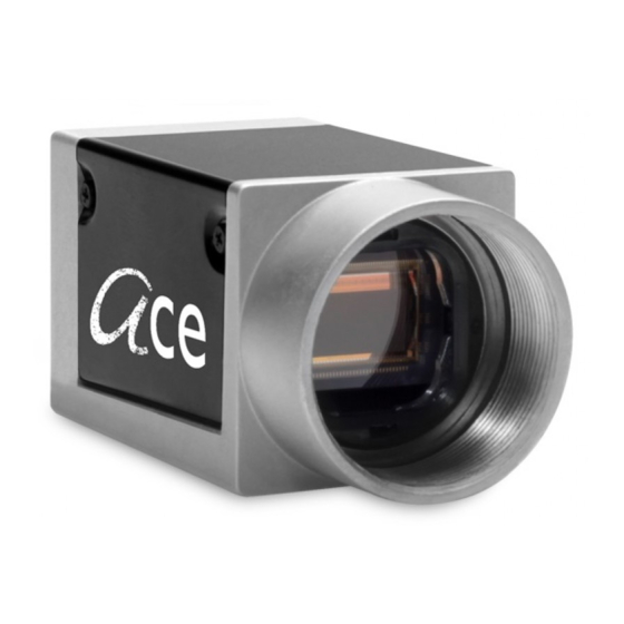
User Manuals: Basler ace acA640-90gm Industrial Camera
Manuals and User Guides for Basler ace acA640-90gm Industrial Camera. We have
2
Basler ace acA640-90gm Industrial Camera manuals available for free PDF download: User Manual
Basler ace acA640-90gm User Manual (488 pages)
GigE CAMERAS
Brand:
Basler
| Category:
Digital Camera
| Size: 4 MB
Table of Contents
Warranty Information
3
Contacting Basler Support Worldwide
4
Table of Contents
5
Specifications, Requirements, and Precautions
12
Camera Models
12
Specification Notes
13
Sensor Size
13
Max. Frame Rate
13
General Specifications of Camera Models
14
Cameras with CCD Sensor
14
Cameras with CMOS Sensors
22
Spectral Response
51
Mono Camera Spectral Response
51
Color Camera Spectral Response
60
Mechanical Specifications
69
Camera Dimensions and Mounting Points
69
Maximum Allowed Lens Thread Length
71
Mechanical Stress Test Results
73
Software Licensing Information
74
LWIP TCP/IP Licensing
74
LZ4 Licensing
75
Avoiding EMI and ESD Problems
76
Environmental Requirements
77
Temperature and Humidity
77
Heat Dissipation
77
Over Temperature Behavior
78
Operation in over Temperature Mode
79
Cooling Path
80
Monitoring the Internal Temperature
81
Precautions
82
Installation
86
Software and Accessories
87
Basler Pylon Camera Software Suite
87
Pylon Viewer
87
Basler Pylon IP Configurator
88
Pylon Sdks
88
Accessories
89
Camera Functional Description
90
Overview Global Shutter with CCD Sensor
90
Overview Global Shutter with CMOS Sensor
93
Overview Rolling Shutter with CMOS Sensor
95
Cameras with Switchable Shutter Mode
97
Cameras that Can Switch between Rolling and Global Shutter Mode
97
Cameras that Can Switch between Rolling Shutter and Global Reset Release Shutter Mode
98
Physical Interface and I/O Control
99
Camera Connector Types
99
Which Camera Model Has GPIO
100
Camera Connector Pin Numbering and Assignments
101
I/O Connector Pin Numbering and Assignments
101
Ethernet Connector Pin Numbering and Assignments
102
Camera Cabling Requirements
102
Ethernet Cable
102
I/O Cable
102
Camera Power
104
Opto-Isolated Input (Pin 2)
106
Electrical Characteristics
106
Opto-Isolated Output (Pin 4)
109
Electrical Characteristics
109
General Purpose I/O (Only Available for Certain Cameras)
113
Introduction
113
Operation as an Input
115
Electrical Characteristics
115
Operation as an Output
117
Electrical Characteristics
117
Temporal Performance of I/O Lines
119
Introduction
119
Factors Determining I/O Temporal Performance
122
Recommendations for Using Camera I/Os
123
Configuring the Input Line
124
Selecting the Input Line as the Source Signal for a Camera Function
124
Input Line Debouncer
125
Setting the Input Line for Invert
127
Configuring the Output Line
128
Selecting a Source Signal for the Output Line
128
Minimum Output Pulse Width
130
Setting the State of a User Settable Output Line
132
Setting and Checking the State of All User Settable Output Lines
133
Setting the State of a User Settable Synchronous Output Signal
135
Setting and Checking the State of All User Settable Synchronous
137
Output Signals
137
Setting the Output Line for Invert
139
Working with the Timer Output Signal
140
Setting the Trigger Source for the Timer
141
Setting the Timer Delay Time
141
Setting the Timer Duration Time
143
Checking the State of the I/O Lines
146
Checking the State of the Output Line
146
Checking the State of All Lines
147
Image Acquisition Control
148
Overview
149
Acquisitionstart and Acquisitionstop Commands and the Acquisitionmode
153
The Acquisition Start Trigger
155
Acquisition Start Trigger Mode
155
Acquisition Start Trigger Mode = off
156
Acquisition Start Trigger Mode = on
156
Acquisition Frame Count
157
Setting the Acquisition Start Trigger Mode and Related Parameters
158
Using a Software Acquisition Start Trigger
159
Introduction
159
Setting the Parameters Related to Software Acquisition Start Triggering and Applying a Software Trigger Signal
159
Using a Hardware Acquisition Start Trigger
161
Introduction
161
Setting the Parameters Related to Hardware Acquisition Start Triggering and Applying a Hardware Trigger Signal
161
The Frame Start Trigger
163
Trigger Mode
164
Frame Start Trigger Mode = off (Free Run)
164
Triggermode = on (Software or Hardware Triggering)
165
Setting the Frame Start Trigger Mode and Related Parameters
166
Using a Software Frame Start Trigger
167
Introduction
167
Setting the Parameters Related to Software Frame Start Triggering and Applying a Software Trigger Signal
168
Using a Hardware Frame Start Trigger
170
Introduction
170
Exposure Modes
171
Timed Exposure Mode
171
Trigger Width Exposure Mode
172
Frame Start Trigger Delay
176
Setting the Parameters Related to Hardware Frame Start Triggering and Applying a Hardware Trigger Signal
176
Aca750 - Acquisition Control Differences
178
Overview
178
Field Output Modes
180
Setting the Field Output Mode
183
Setting the Exposure Time
184
Electronic Shutter Operation
187
Global Shutter
188
Rolling Shutter Mode
190
Global Reset Release Mode
193
Setting the Shutter Mode
195
Setting the Shutter Mode (Camera Models See † in Table 37)
195
Setting the Shutter Mode (Aca1920-25, Aca2500-14)
196
The Flash Window
197
Sensor Readout Mode
201
Overlapping Image Acquisitions - (Models with Global Shutter)
202
Overlapping Image Acquisitions - (Models with Rolling Shutter)
205
Acquisition Monitoring Tools
209
Exposure Active Signal
209
Flash Window Signal
212
Acquisition Status Indicator
214
Trigger Wait Signals
215
Acquisition Trigger Wait Signal
215
The Frame Trigger Wait Signal
218
Camera Events
224
Acquisition Timing Chart
225
Frame Acquisitions Frame Acquisitions Not Overlapped Overlapped
226
Maximum Allowed Frame Rate
229
Using Basler Pylon to Check the Maximum Allowed Frame Rate
230
Increasing the Maximum Allowed Frame Rate
230
Sensor Readout Modes on Certain Cameras
232
Removing the Frame Rate Limit (Aca640-120 Only)
234
Use Case Descriptions and Diagrams
235
Pixel Formats
243
Setting Pixel Format Parameter Values
243
Pixel Data Output Formats: some Details for Color Cameras
244
Features
246
Gain
246
Analog and Digital Control
247
Aca640-90Gm/Gc
247
Aca640-120Gm/Gc
247
Setting the Gain
248
Aca640-300Gm/Gc
248
Aca645-100Gm/Gc
250
Aca750-30Gm/Gc
250
Aca780-75Gm/Gc
250
Aca800-200Gm/Gc
250
Analog Gain
253
Digital Gain
253
Black Level
255
Setting the Black Level
256
Remove Parameter Limits
258
Digital Shift
260
Enabling and Setting Digital Shift
263
Image Area of Interest (AOI)
264
Setting the AOI
265
Center X and Center y
268
Changing AOI Parameters "On-The-Fly
268
Stacked Zone Imaging
269
Setting Stacked Zone Imaging
272
Error Codes
274
Precision Time Protocol (IEEE 1588)
276
Enabling PTP Clock Synchronization
279
Checking the Status of the PTP Clock Synchronization
281
Code Example
282
How to Check When a Camera Is Synchronized to a Master
283
Action Commands
285
Action Command Example Setup
285
Action Command Parameters
287
Using Action Commands
288
Synchronous Image Acquisition
288
Synchronous Frame Counter Reset
291
Synchronous Sequence Set Advance
292
Scheduled Action Commands
295
Scheduled Action Command Parameters
295
Using Scheduled Action Commands
296
Synchronous Free Run
298
Synchronous Free Run Parameters
301
Using Synchronous Free Run
302
Sequencer
304
Auto Sequence Advance Mode
311
Operation
311
Configuration
314
Controlled Sequence Advance Mode
315
Operation with the "Always Active" Sequence Control Source
316
Operation with the Input Line as Sequence Control Source
321
Operation with the Sequencecontrolsource Set to Disabled
324
Configuration
328
Free Selection Sequence Advance Mode
332
Operation
332
Configuration
336
Binning
338
Binning Modes
339
Setting Binning Parameters
340
Setting the Binning Mode
342
Considerations When Using Binning
342
Decimation
345
Vertical Decimation
345
Horizontal Decimation
347
Considerations When Using Decimation
348
Scaling
349
Setting Scaling
350
Considerations When Using Scaling
350
Mirror Imaging
352
Reverse X
353
Reverse y
355
Enabling Reverse X and Reverse y
356
Gamma Correction
357
Color Creation and Enhancement
359
How to Obtain Good Color Settings in Your Camera
359
How to Obtain Best Color Settings in Your Camera
359
How to Obtain Raw Settings and Low Noise in Your Camera
360
Color Creation (All Color Models Except the Aca750-30Gc)
361
Bayer Color Filter Alignment
362
Pixel Formats Available on Cameras with a Bayer Filter
363
Color Creation on the Aca750-30Gc
364
Pixel Formats Available on Cameras with a Cmyeg Filter
366
Integrated IR Cut Filter
367
Color Enhancement Features
368
Color Enhancement-Related Wake-Up Values of the Cameras
368
Balance White
370
Setting the White Balance
370
PGI Feature Set
373
Noise Reduction
374
Sharpness Enhancement
374
Light Source Presets
376
Color Adjustment
378
Color Transformation
383
The Custom Light Source Setting
385
Color Transformation on Aca750-30Gc Cameras
387
Luminance Lookup Table
388
Auto Functions
392
Common Characteristics
392
Auto Function Operating Modes
393
Auto Function Aois
394
Assignment of an Auto Function to an Auto Function AOI
395
Positioning of an Auto Function AOI Relative to the Image AOI
396
Setting an Auto Function AOI
398
Gain Auto
399
Exposure Auto
401
Gray Value Adjustment Damping
404
Auto Function Profile
405
Balance White Auto
406
Balance White Adjustment Damping
407
Pattern Removal
408
Monochrome Cameras
408
Color Cameras
411
Using an Auto Function
411
Median Filter
412
Event Notification
413
Test Images
416
Test Image Descriptions
418
Device Information Parameters
420
User-Defined Values
422
Configuration Sets
423
The Color Factory Set
425
The "Raw Color" Factory Set
426
Saving a User Set
427
List of Parameters that Are Not Saved in a User Set
427
Loading a User Set or a Factory Set into the Active Set
428
Designating the Startup Set
429
Chunk Features
430
What Are Chunk Features
430
Chunk Mode Active and Enabling the Extended Data Chunk
431
Data Chunks
432
Gain All Chunk
432
Line Status All Chunk
432
Exposure Time Chunk
433
Timestamp Chunk
434
Frame Counter Chunk
434
Trigger Input Counter Chunk
436
CRC Checksum Chunk
438
Sequence Set Index Chunk
439
Extended Image Chunks
441
Retrieving Data Chunks
442
Troubleshooting and Support
443
Tech Support Resources
443
Obtaining an RMA Number
443
Before Contacting Basler Technical Support
444
Appendix A Basler Network Drivers and Parameters
446
The Basler Filter Driver
447
The Basler Performance Driver
448
General Parameters
449
Threshold Resend Mechanism Parameters
449
Timeout Resend Mechanism Parameters
451
Threshold and Timeout Resend Mechanisms Combined
453
Adapter Properties
455
Transport Layer Parameters
456
Appendix B Network Related Camera Parameters and Managing Bandwidth
457
Network Related Parameters in the Camera
457
Managing Bandwidth When Multiple Cameras Share a Single Network Path
464
A Procedure for Managing Bandwidth
466
Revision History
471
Index
485
Advertisement
Basler ace acA640-90gm User Manual (302 pages)
GigE CAMERAS
Brand:
Basler
| Category:
Digital Camera
| Size: 3 MB
Table of Contents
Table of Contents
5
1 Specifications, Requirements, and Precautions
11
Models
11
General Specifications
12
Spectral Response
18
Mono Camera Spectral Response
18
Color Camera Spectral Response
22
Mechanical Specifications
26
Camera Dimensions and Mounting Points
26
Maximum Allowed Lens Thread Length
27
Software Licensing Information
28
Avoiding EMI and ESD Problems
29
Environmental Requirements
30
Temperature and Humidity
30
Heat Dissipation
30
Precautions
31
2 Installation
35
3 Camera Drivers and Tools for Changing Camera Parameters
37
The Pylon Driver Package
37
The Pylon Viewer
38
The Pylon IP Configuration Tool
38
The Pylon API
38
4 Camera Functional Description
39
Overview (All Models Except Aca2500-14)
39
Overview (Aca2500-14 Only)
42
5 Physical Interface
45
General Description of the Camera Connections
45
Camera Connector Pin Assignments and Numbering
46
6-Pin Receptacle Pin Assignments & Numbering
46
Jack Pin Assignments & Numbering
47
Camera Connector Types
47
8-Pin RJ-45 Jack
47
6-Pin Connector
47
Camera Cabling Requirements
48
Ethernet Cables
48
Standard Power and I/O Cable
48
PLC Power and I/O Cable
50
Camera Power
51
Ethernet Gige Device Information
52
Input Line Description
53
Voltage Requirements
53
Characteristics
54
Response Time
55
Selecting the Input Line as the Source Signal for a Camera Function
56
Output Line Description
57
Voltage Requirements
57
Characteristics
57
Response Time
60
Selecting a Source Signal for the Output Line
60
6 O Control
61
Configuring the Input Line
61
Selecting the Input Line as the Source Signal for a Camera Function
61
Input Line Debouncer
62
Setting the Input Line for Invert
63
Configuring the Output Line
64
Selecting a Source Signal for the Output Line
64
Setting the State of a User Settable Output Line
65
Setting the Output Line for Invert
66
Working with the Timer Output Signal
67
Setting the Trigger Source for the Timer
67
Setting the Timer Delay Time
68
Setting the Timer Duration Time
70
Checking the State of the I/O Lines
72
Checking the State of the Output Line
72
Checking the State of All Lines
72
7 Image Acquisition Control
73
Overview
73
Acquisition Start and Stop Commands and the Acquisition Mode
77
The Acquisition Start Trigger
79
Acquisition Start Trigger Mode
79
Acquisition Start Trigger Mode = off
79
Acquisition Start Trigger Mode = on
79
Acquisition Frame Count
80
Setting the Acquisition Start Trigger Mode and Related Parameters
81
Using a Software Acquisition Start Trigger
82
Introduction
82
Setting the Parameters Related to Software Acquisition Start Triggering and Applying a Software Trigger Signal
82
Using a Hardware Acquisition Start Trigger
84
Introduction
84
Setting the Parameters Related to Hardware Acquisition Start Triggering and Applying a Hardware Trigger Signal
84
The Frame Start Trigger
86
Frame Start Trigger Mode
86
Frame Start Trigger Mode = off
86
Frame Start Trigger Mode = on
87
Setting the Frame Start Trigger Mode and Related Parameters
88
Using a Software Frame Start Trigger
90
Introduction
90
Setting the Parameters Related to Software Frame Start Triggering and Applying a Software Trigger Signal
91
Using a Hardware Frame Start Trigger
92
Introduction
92
Exposure Modes
93
Frame Start Trigger Delay
95
Setting the Parameters Related to Hardware Frame Start Triggering and Applying a Hardware Trigger Signal
95
Aca-750 Acquisition Control Differences
97
Overview
97
Field Output Modes
99
Setting the Field Output Mode
102
Setting the Exposure Time
103
Electronic Shutter Operation
105
Global Shutter (All Cameras Except Aca2500Gm/Gc)
105
Rolling Shutter (Aca2500Gm/Gc Only)
107
The Flash Window
110
Overlapping Exposure with Sensor Readout (All Models Except Aca2500-14Gm/Gc)
114
Overlapping Image Acquisitions (Aca2500-14 Gm/Gc Only)
117
Acquisition Monitoring Tools
120
Exposure Active Signal
120
Flash Window Signal
122
Acquisition Status Indicator
124
Trigger Wait Signals
125
Acquisition Trigger Wait Signal
125
The Frame Trigger Wait Signal
127
Acquisition Timing Chart
133
Maximum Allowed Frame Rate
136
Using Basler Pylon to Check the Maximum Allowed Frame Rate
137
Increasing the Maximum Allowed Frame Rate
137
Removing the Frame Rate Limit (Aca640-100 Only)
139
Use Case Descriptions and Diagrams
140
8 Color Creation and Enhancement
149
Color Creation (All Color Models Except the Aca750-Gc)
149
Bayer Color Filter Alignment
150
Pixel Data Formats Available on Cameras with a Bayer Filter
150
Color Creation on the Aca750-30Gc
152
Pixel Data Formats Available on Cameras with a Cmyeg Filter
155
Integrated IR Cut Filter (All Color Models)
156
Color Enhancement Features on Aca640-90Gc, Aca640-100Gc and Aca1300-30Gc
157
Cameras
157
White Balance
157
Gamma Correction
158
Color Enhancement Features on Aca750-30Gc and Aca2500-14Gc Cameras
160
White Balance
160
Gamma Correction
161
Matrix Color Transformation
163
Matrix Transformation Custom Mode
165
Color Adjustments
167
A Procedure for Setting the Color Enhancements
171
9 Pixel Data Formats
173
Setting the Pixel Data Format
173
Pixel Data Formats for Mono Cameras
175
Mono 8 Format
175
Mono 12 Format
176
Mono 12 Packed Format
178
YUV 4:2:2 Packed Format
180
YUV 4:2:2 (YUYV) Packed Format
180
Pixel Data Output Formats for Color Cameras
181
Bayer BG 8 Format
181
Bayer BG 12 Format
183
Bayer BG 12 Packed Format
185
YUV 4:2:2 Packed Format
187
YUV 4:2:2 (YUYV) Packed Format
189
Mono 8 Format
191
Pixel Transmission Sequence
193
10 Standard Features
195
Gain
195
Setting the Gain
196
Black Level
199
Setting the Black Level
200
Remove Parameter Limits
201
Digital Shift
203
Digital Shift with 12 Bit Pixel Formats
203
Digital Shift with 8 Bit Pixel Formats
205
Precautions When Using Digital Shift
207
Enabling and Setting Digital Shift
208
Image Area of Interest (AOI)
209
Changing AOI Parameters "On-The-Fly
211
Binning
212
Considerations When Using Binning
213
Reverse X
215
Luminance Lookup Table
218
Auto Functions
221
Common Characteristics
221
Auto Function Operating Modes
222
Auto Function Aois
223
Using an Auto Function
227
Gain Auto
228
Exposure Auto
230
Auto Function Profile
232
Balance White Auto
233
Event Reporting
234
Test Images
237
Test Image Descriptions
238
Device Information Parameters
241
User Defined Values
243
Configuration Sets
244
Selecting a Factory Setup as the Default Set
246
Saving a User Set
247
Loading the User Set or the Default Set into the Active Set
248
Selecting the Startup Set
249
11 Chunk Features
251
What Are Chunk Features
251
Making the "Chunk Mode" Active and Enabling the Extended Data Stamp
252
Frame Counter
254
Time Stamp
257
Trigger Input Counter
258
Line Status All
261
CRC Checksum
263
12 Troubleshooting and Support
265
Tech Support Resources
265
Obtaining an RMA Number
265
Before Contacting Basler Technical Support
266
Appendix A Basler Network Drivers and Parameters
269
The Basler Filter Driver
270
The Basler Performance Driver
271
General Parameters
272
Threshold Resend Mechanism Parameters
272
A.2.1 General Parameters
272
Timeout Resend Mechanism Parameters
274
Threshold and Timeout Resend Mechanisms Combined
276
Adapter Properties
278
A.2.5 Adapter Properties
278
Transport Layer Parameters
279
Appendix B Network Related Camera Parameters and Managing Bandwidth
281
Network Related Parameters in the Camera
281
Managing Bandwidth When Multiple Cameras Share a Single Network Path
288
A Procedure for Managing Bandwidth
290
Revision History
295
Index
297
Advertisement
Related Products
Basler ace acA640-90gc
Basler ace acA640-100gm
Basler ace acA640-100gc
Basler acA640-120um/uc
Basler GIGE VISION ace acA640-100gm/gc
Basler acA2040-55
Basler acA2040-120
Basler acA2440-75
Basler acA1300-30um/uc
Basler acA2500-14um/uc
Basler Categories
Relays
Digital Camera
Controller
Security Camera
Protection Device
More Basler Manuals
Login
Sign In
OR
Sign in with Facebook
Sign in with Google
Upload manual
Upload from disk
Upload from URL