Sign In
Upload
Manuals
Brands
Baldor Manuals
Controller
MintDrive
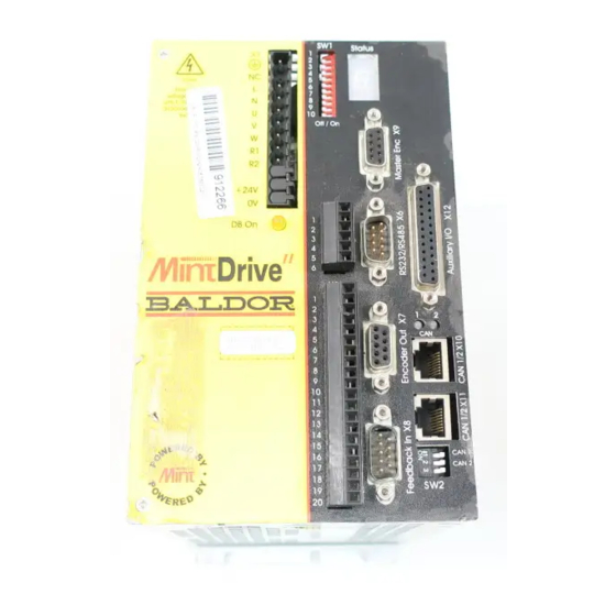
Baldor MintDrive Servo Control Module Manuals
Manuals and User Guides for Baldor MintDrive Servo Control Module. We have
1
Baldor MintDrive Servo Control Module manual available for free PDF download: Installation Manual
Baldor MintDrive Installation Manual (155 pages)
Brand:
Baldor
| Category:
Controller
| Size: 4 MB
Table of Contents
Table of Contents
8
1 Introduction
14
Mintdrive Features
14
Receiving and Inspection
15
Identifying the Catalog Number
15
Mintdrive Indicators
16
Monitor LED Display
16
CAN 1 and 2 Leds
16
Ready LED
16
DB on (Regeneration Load) LED
16
Units and Abbreviations
17
2 Basic Installation
18
Outline
18
Hardware Requirements
18
RS485 / RS422 Systems
20
Power Sources
20
Tools and Miscellaneous Hardware
20
Other Information Needed for Installation
20
Mechanical Installation and Location Requirements
21
Dimensions and Mounting
22
Power Connections
23
Grounding
24
Input Power Conditioning
25
Power Disconnect and Protection Devices
25
Wire Sizes
27
Single Phase Connection to Package Size a or B
28
Single Phase Connection to Package Size C
28
Three Phase Connection to Package Size C
29
Control Supply
29
DC Bus Power Connections from Package Size C
30
2.3.10 Power Supply Filters
31
Motor Connections
32
Motor Circuit Contactors
33
Regeneration Resistor (Dynamic Brake Resistor)
34
Feedback Connections
35
Resolver Option
36
Encoder Option
38
Drive Enable
39
3 Input / Output
40
Outline
40
Analog I/O
40
Analog Input, Single Ended - X11
41
Analog Input, Differential - X11
42
Analog Inputs, Differential - X5
43
Analog Outputs, Bipolar - X11
45
Analog Outputs, Bipolar - X5
46
Digital I/O
47
Digital Inputs - X13
48
Digital Inputs - X5
50
Digital Outputs - X13
52
Digital Outputs - X5
53
Other I/O
54
Simulated Encoder Output - X3
54
Master (Auxiliary) Encoder Input - X6
55
Serial Port - X7
57
Using RS232 Cable
58
Multidrop Using RS485 / RS422 Cable
59
Connecting Baldor HMI Operator Panels
60
Optional Breakout Board for Connector X5
61
CAN Peripherals
61
4 Tuning and Configuration
62
Outline
62
Connecting the Mintdrive to the PC
62
Installing the Software
62
Starting the Mintdrive
63
Mint Configuration Tool Startup Wizard - Coarse Tuning
64
MCT Startup Wizard - Fine-Tuning
67
An Introduction to Closed Loop Control
67
Fine-Tuning the Speed Loop
69
Fine-Tuning the Position Loop
70
Jog Test
72
Completing the Startup Wizard
73
MCT Wizard - Hardware Configuration
74
Digital Input Configuration
74
Digital Output Configuration
75
Axis0 Parameter Configuration
76
Axis0 Error Configuration
76
Axis0 Tuning Configuration
77
Miscellaneous Configuration
77
Completing the Configuration Wizard
78
5 Mint Workbench
80
Outline
80
Completing Configuration
80
Using Workbench
81
Selecting the Controller
81
Menus and Buttons
81
Watch Window
83
Quick Watch Tab
83
Speed Loop Tab
84
Position Loop Tab
85
Capture Tab
86
Editor Windows
87
Configuration Window
87
Program Window
87
Terminal Window
88
Useful Commands for Testing
88
Firmware Update
90
6 Specifications
92
Outline
92
General Specifications
92
Power
93
Rectifier and Regeneration
94
Resolver Feedback
94
Encoder Feedback
95
Control Signals
95
Environmental
96
7 Troubleshooting
98
Outline
98
Problem Diagnosis
98
Communication
99
Power up
100
Tuning
102
Mint Gains
103
Ready LED Is Red
104
Can
107
A Tuning
110
Introduction
110
Closed Loop Control
112
Position Loop
113
A.1.2 Position Loop
113
Speed Loop
114
Current Loop
114
Mintdrive Operational Modes
114
A.1.3 Speed Loop
114
Tuning the Position Loop for a Velocity Servo Drive
115
Tuning the Position Loop for a Servo Drive
115
Tuning the Position Loop for a Torque Servo Drive
118
Saving Tuning Information
118
Bcan
120
Outline
120
Mintdrive Capabilities
120
B.1 Outline
120
CAN 1 (Canopen)
122
CAN 1 (Canopen) - X9
122
B.2 CAN 1 (Canopen)
122
What Is Canopen
123
B.2.2 What Is Canopen
123
Configuring Nodes
124
Network Manager - Node 1
124
Scanning Nodes
124
B.2.3 Configuring Nodes
124
Connecting to Nodes
125
B.2.6 Connecting to Nodes
125
Monitoring CAN Events
126
Controller Nodes
127
B.2.8 Controller Nodes
127
I/O Nodes
128
B.2.9 I/O Nodes
128
B.2.10 HMI Operator Panels
130
CAN 2 (Baldor CAN)
132
CAN 2 (Baldor CAN) - X8
132
Preparing the Mintdrive
133
Preparing the CAN Peripheral
133
Connecting the PC, Mintdrive and CAN Peripheral
133
Node Ids
134
Static Configuration
134
B.3.5 Node Ids
134
Adding the Node to the Network
135
Monitoring CAN Bus Communications
136
Controlling the CAN Peripheral
136
B.3.10 Normal Operation
136
B.3.11 Keypadnode
137
Ionode 24/24
138
B.3.12 Ionode 24/24
138
B.3.13 Example CAN Network
139
B.3.14 Mint CAN Related Keywords
140
CCE Guidelines
142
Outline
142
Declaration of Conformity
142
C.1 Outline
142
EMC Conformity and CE Marking
143
Use of CE Compliant Components
143
EMC Wiring Technique
143
EMC Installation Suggestions
144
Wiring of Shielded (Screened) Cables
145
Accessories and Options
148
Outline
148
Cables
148
D.1 Outline
148
Resolver Feedback Cable
149
EMC Mains Filters
150
Regeneration Resistors
152
D.1.4 Regeneration Resistors
152
Breakout Board - X5
153
D.1.5 Breakout Board - X5
153
Advertisement
Advertisement
Related Products
Baldor MDH1A05TB-RC23
Baldor MintDrive II
Baldor MicroFlex
Baldor MN785
Baldor Modbus Plus
Baldor MotiFlex e100
Baldor MAV30
Baldor MAH30
Baldor MDH2A07TR-RB23
Baldor MN427
Baldor Categories
Controller
Inverter
Engine
Portable Generator
Servo Drives
More Baldor Manuals
Login
Sign In
OR
Sign in with Facebook
Sign in with Google
Upload manual
Upload from disk
Upload from URL