AUMA SAEx 25.1 Manuals
Manuals and User Guides for AUMA SAEx 25.1. We have 5 AUMA SAEx 25.1 manuals available for free PDF download: Operation Instructions Manual, Operation Manual, Manual

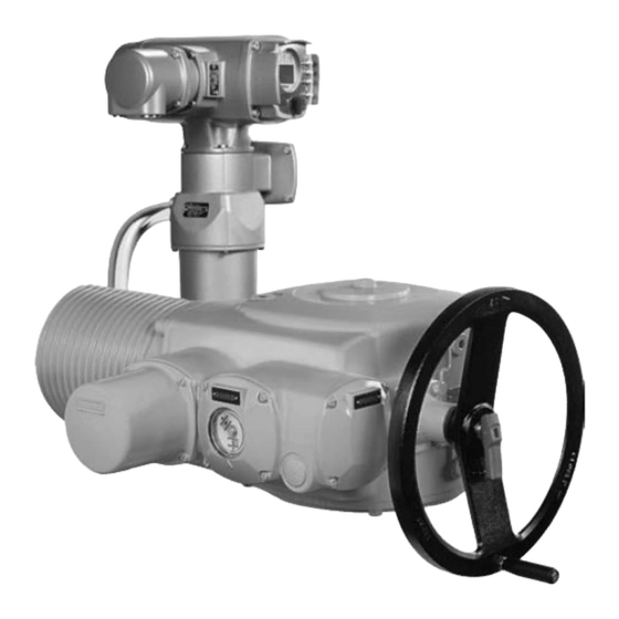
AUMA SAEx 25.1 Operation Instructions Manual (112 pages)
Multi-turn actuators, Control unit - electromechanical with actuator controls, on wall bracket
Brand: AUMA
|
Category: Controller
|
Size: 3 MB
Table of Contents
Advertisement

AUMA SAEx 25.1 Operation Manual (100 pages)
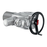
Multi-turn actuators
Brand: AUMA
|
Category: Controller
|
Size: 2 MB
Table of Contents

AUMA SAEx 25.1 Operation Manual (72 pages)
Multi-turn actuators
Brand: AUMA
|
Category: Controller
|
Size: 2 MB
Table of Contents
Advertisement
AUMA SAEx 25.1 Operation Instructions Manual (56 pages)
Multi-turn actuators
Brand: AUMA
|
Category: Controller
|
Size: 1 MB
Table of Contents
AUMA SAEx 25.1 Manual (48 pages)
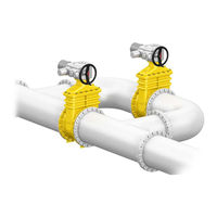
Multi-turn actuators with actuator controls
Brand: AUMA
|
Category: Controller
|
Size: 1 MB
Table of Contents
Advertisement