ADTRAN 1181113L2 Manuals
Manuals and User Guides for ADTRAN 1181113L2. We have 2 ADTRAN 1181113L2 manuals available for free PDF download: Installation And Maintenance Practice
ADTRAN 1181113L2 Installation And Maintenance Practice (90 pages)
HDSL2 for general distribution
Table of Contents
Advertisement
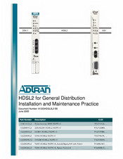
ADTRAN 1181113L2 Installation And Maintenance Practice (90 pages)
HDSL2 for General Distribution
Brand: ADTRAN
|
Category: Network Hardware
|
Size: 2 MB
Table of Contents
Advertisement