Sign In
Upload
Manuals
Brands
ABB Manuals
Touch terminals
REL 551 2.5
ABB REL 551 2.5 Manuals
Manuals and User Guides for ABB REL 551 2.5. We have
2
ABB REL 551 2.5 manuals available for free PDF download: Installation And Commissioning Manual, Operator's Manual
ABB REL 551 2.5 Installation And Commissioning Manual (184 pages)
Differential protection terminal
Brand:
ABB
| Category:
Protection Device
| Size: 3.38 MB
Table of Contents
Table of Contents
4
Chapter 1 Introduction
10
Introduction to the Installation and Commissioning Manual
11
About the Complete Set of Manuals for a Terminal
11
About the Installation and Commissioning Manual
11
Intended Audience
12
General
12
Requirements
12
Related Documents
13
Revision Notes
13
Acronyms and Abbreviations
13
Chapter 2 Safety Information
22
Warning Signs
23
Caution Signs
25
Note Signs
26
Chapter 3 Overview
28
Commissioning and Installation Overview
29
Chapter 4 Unpacking and Checking the Terminal
30
Receiving, Unpacking and Checking
31
Chapter 5 Installing the Terminal
32
Overview
33
Mounting the Terminal
34
Mounting in a 19-Inch Rack
35
Mounting in a 19-Inch Rack with an Additional Box Type RHGS
36
Mounting in a Flush or Semi-Flush Installation
37
Mounting on a Wall
39
Mounting the Terminal on a Wall
40
Preparing a Wall Mounted Terminal for Electrical Installation
41
Making the Electrical Connections
42
Connecting the CT Circuits
42
Connecting the Auxiliary Power, VT and Signal Connectors
42
Connecting to Protective Earth
44
Making the Screen Connection
44
Installing the Optical Fibres
45
Installing the Serial Communication Cable for RS485 SPA/IEC
46
RS485 Serial Communication Module
46
Informative Excerpt from EIA Standard RS-485
48
Data on RS485 Serial Communication Module Cable
50
Installing the 56/64 Kbit Data Communication Cables
51
Chapter 6 Checking the External Circuitry
54
Overview
55
Checking the CT and VT Circuits
56
Checking the Power Supply
57
Checking the Binary I/O Circuits
58
Binary Input Circuits
58
Binary Output Circuits
58
Chapter 7 Energising the Terminal
60
Overview
61
Energising the Terminal
62
Checking the Self Supervision Signals
64
Reconfiguring the Terminal
64
Setting the Terminal Time
64
Checking the Self Supervision Function
64
Navigating the Menus
64
Self Supervision HMI Data
65
Chapter 8 Configuring the 56/64 Kbit Data Communication Modules
66
Configuring the Fibre Optical Modem
67
Calculation of Optical Power Budget
68
Configuring the Short Range Fibre Optical Modem
69
Configuring the Short Range Galvanic Modem
73
Configure the Interface Modules for V.36, X.21 and RS530
75
Configuring the Interface Modules for G.703 Co-Directional
77
Fault Tracing
78
Comfail Function
78
Explanation of Contents in Column 2 of Table 42
79
Configuring the Transceiver 21-15Xx
82
Co-Directional Operation
83
Contra-Directional Operation
85
Configuring the Transceiver 21-16Xx
87
X.21 Operation
87
G.703 Co-Directional Operation
88
Chapter 9 Setting and Configuring the Terminal
90
Overview
91
Entering Settings through the Local HMI
92
Configuring the Setting Restriction of HMI Function
93
Activating the Restriction of Setting
94
Local HMI
94
Serial Communication, Change of Active Group
94
Serial Communication, Setting
94
Downloading Settings and Configuration from a PC
95
Establishing Front Port Communication
95
Establishing Rear Port Communication
95
Using the SPA/IEC Rear Port
95
Using LON Rear Port
96
Downloading the Configuration and Setting Files
96
Chapter 10 Requirement of Trig Condition for Disturbance Report
98
Requirement of Trig Condition for Disturbance Report
99
Chapter 11 Establishing Connection and Verifying the
100
SPA/IEC-Communication
100
Entering Settings
101
Entering IEC Settings
101
Entering SPA Settings
101
Verifying the Communication
103
Verifying IEC Communication
103
Verifying SPA Communication
103
Optical Budget Calculation for Serial Communication with SPA/IEC
104
Chapter 12 Establishing Connection and Verifying the LON Communication
106
Reference
107
Verification of the Optical Budget
107
Optical Budget Calculation for Serial Communication with LON
107
Chapter 13 Verifying Settings by Secondary Injection
108
Overview
109
Preparing for Test
111
Overview
111
Preparing the Connection to the Test Equipment
111
Setting the Terminal in Test Mode
112
Connecting Test Equipment to the Terminal
112
Verifying the Connection and the Analog Inputs
113
Releasing the Function(S) to be Tested
114
Checking the Disturbance Report Settings
114
Identifying the Function to Test in the Technical Reference Manual
115
Autorecloser (AR)
116
Preparing
117
Checking the AR Functionality
118
Checking the Reclosing Condition
118
Checking the Breaker Not Ready
119
Checking the Closing Onto a Fault
119
Checking the Inhibit Signal
119
Checking the Operation Stand-By and off
119
Checking the Synchro-Check Condition (for Three-Phase Reclosing Cycle)
119
Testing the Multi-Breaker Arrangement
120
Completing the Test
120
Breaker Failure Protection (BFP)
121
Verifying the Settings
121
Verifying the Retrip Setting
121
Checking the Retrip Function with Current Check
121
Checking the Retrip Function with Retrip Set to off
121
Checking the Retrip Function Without Current Check
122
Completing the Test
122
Broken Conductor Check (BRC)
123
Measuring the Operate and Time Limit of Set Values
123
Communication Channel Test Logic (CCHT)
124
Testing the Logic
124
Current Circuit Supervision (CTSU)
125
Time Delayed Residual Overcurrent Protection (TEF)
126
Checking the Operate Values of the Current Measuring Elements
126
Disturbance Recorder (DR)
129
Event Counter (CN)
130
Event Function (EV)
131
Event Recorder (ER)
132
Instantaneous Non-Directional Overcurrent Protection (IOC)
133
Measuring the Operate Limit of Set Values
133
Phase Overcurrent Protection
133
Residual Overcurrent Protection (Non-Dir.)
133
Completing the Test
133
Line Differential Protection, Phase Segregated (DIFL)
134
Testing the Line Differential Protection
136
Testing the Charging Current Compensation
138
Completing the Test
139
Supervision of AC Input Quantities (DA)
140
Verifying the Settings
140
Completing the Test
140
Supervision of Ma Input Quantities (MI)
141
Verifying the Settings
141
Completing the Test
142
Multiple Command (CM)
143
Overload Supervision (OVLD)
144
Measuring the Operate and Time Limit of Set Values
144
Pole Discordance Protection (PD)
146
Pulse Counter Logic for Metering (PC)
147
Setting Lockout (HMI)
148
Verifying the Settings
148
Completing the Test
148
Four Parameter Setting Groups (GRP)
149
Verifying the Settings
149
Single Command (CD)
150
Thermal Phase Overload Protection (THOL)
151
Measuring the Operate and Time Limit of Set Values
151
Testing the Protection Without External Temperature Compensation (Noncomp)
151
Definite Time Non-Directional Overcurrent Protection (TOC)
153
Measuring the Operate Limit of Set Values
153
Time Delayed Phase Overcurrent
153
Time Delayed Residual Overcurrent (Non-Dir.)
153
Completing the Test
154
Tripping Logic (TR)
155
3Ph Operating Mode
155
1Ph/3Ph Operating Mode
155
1Ph/2Ph/3Ph Operating Mode
156
Completing the Test
157
Two Step Time Delayed Non-Directional Phase Overcurrent Protection (TOC2)
158
Measuring the Operate and Time Limit for Set Values
158
Measuring the Definite Time Delay of the Low Set Stage
158
Measuring the Inverse Time Delay of the Low Set Stage
158
Measuring the Operate Limit of the Low Step Overcurrent Protection
158
Measuring the Operate Limit of the High Step Overcurrent Protection
159
Completing the Test
159
Sudden Change in Phase Current Protection (SCC1)
160
Measuring the Operate Limit of Set Values
160
Dependability Test
160
Sudden Change in Current in any Phase
160
Time Delay Test
160
Completing the Test
161
Sudden Change in Residual Current Protection (SCRC)
162
Measuring the Operate Limit of Set Values
162
Dependability Test
162
Sudden Change in Residual Current
162
Time Delay Test
162
Completing the Test
163
Undercurrent Protection (UCP)
164
Measuring the Operate Limit of Set Values
164
Completing the Test
164
Dependbility Test
164
Time Delay Test
164
Undercurrent in any Phase
164
Phase Overcurrent Protection (OCP)
165
Measuring the Operate Limit of Set Values
165
Completing the Test
165
Dependability Test
165
Overcurrent in any Phase
165
Time Delay Test
165
Residual Overcurrent Protection (ROCP)
166
Dependability Test
166
Measuring the Operate Limit of Set Values
166
Residual Overcurrent
166
Time Delay Test
166
Completing the Test
167
Chapter 14 Verifying the Internal Configuration
168
Overview
169
Testing the Interaction of the Distance Protection
170
Chapter 15 Testing the Protection System
172
Overview
173
Testing the Interaction of the Distance Protection
174
Chapter 16 Fault Tracing and Repair
176
Fault Tracing
177
Using Information on the Local HMI
177
Using Front-Connected PC or SMS
178
Repair Instruction
180
Repair Support
182
Advertisement
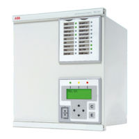
ABB REL 551 2.5 Operator's Manual (88 pages)
ProtectIT Line differential protection terminal
Brand:
ABB
| Category:
Touch terminals
| Size: 2.19 MB
Table of Contents
Table of Contents
4
Kdswhu
5
Introduction to the Operator's Manual
9
Human Machine Interface
11
HMI Module LED Indications
23
8Qghuvwdqg Wkh +0, Wuhh
24
Overview
25
Disturbreport
26
Disturbance
26
Calcdisttoflt
26
Manualtrig
26
Cleardistrep
26
Servicevalues
26
Phasors
26
Functions
26
I/O
26
Activegroup
26
Dqgoh Wkh Glvwxuedqfhv
38
View the Disturbance Summary
39
The Disturbance Summary
39
View the Disturbance Indications
40
Navigate the Menus
40
View the Prefault and Fault Voltages and Currents
42
View Disturbance Trigger Levels
43
Navigate the Menus
45
Navigate the Menus
46
Navigate the Menus
47
Navigate the Menus
49
Test the Leds of the LED Module
50
View the Service Values
53
Navigate the Menus
53
View the Primary and Secondary Phasors
56
Navigate the Menus
57
View the Function Block Variables and Output Signals
58
Navigate the Menus
62
Read the Measured and Calculated Function Values
62
Thermal Overload Temperatures
64
View the I/O Function Block Signals
68
I/O Modules
68
Determine the Active Setting Group
71
Ohdu Wkh Frxqwhuv
72
Navigate the Menus
73
Navigate the Menus
74
Clear the Event Counters
75
Navigate the Menus
75
Find the Reason of an Internal Failure
77
Identify the Terminal
79
Navigate the Menus
79
Read the Terminal Time
81
Navigate the Menus
81
Navigate the Menus
82
Advertisement
Related Products
ABB REL 551-C1*2.5
ABB REL 561*2.5
ABB REL 551-C1 2.3 Series
ABB REL 505-C1 2.3 Series
ABB Protect IT REL 501 2.5 Series
ABB REF 545
ABB RET 54 Series
ABB REB 551-C4 2.5 Series
ABB REM 54
ABB REF 54 Series
ABB Categories
Industrial Equipment
Controller
Measuring Instruments
Battery Charger
DC Drives
More ABB Manuals
Login
Sign In
OR
Sign in with Facebook
Sign in with Google
Upload manual
Upload from disk
Upload from URL