Sign In
Upload
Manuals
Brands
ABB Manuals
Industrial Electrical
ACS880-604
ABB ACS880-604 Manuals
Manuals and User Guides for ABB ACS880-604. We have
2
ABB ACS880-604 manuals available for free PDF download: Hardware Manual
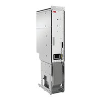
ABB ACS880-604 Hardware Manual (134 pages)
3-Phase brake units as modules
Brand:
ABB
| Category:
Industrial Electrical
| Size: 17.44 MB
Table of Contents
Table of Contents
5
1 Introduction to the Manual
11
Contents of this Chapter
11
Applicability
11
Safety Instructions
11
Target Audience
11
Related Documents
12
Categorization by Frame Size and Option Code
13
Use of Component Designations
13
Terms and Abbreviations
13
2 Operation Principle and Hardware Description
15
Contents of this Chapter
15
Product Overview
15
Operating Principle
15
When to Use Resistor Braking
15
Simplified Main Circuit Diagram of the Drive System
16
Brake Module Hardware
17
General
17
DC Connection and Capacitor Charging
17
Connectors X50
18
Fibre Optic Connectors
19
Overview Circuit Diagram of the Brake Unit
20
Frame R8I Layout
21
Overview of Power and Control Connections
22
Brake Unit Control Devices
23
Overview of the Control Connections of the BCU Control Unit
23
The Control Panel
24
Control by PC Tools
24
Fieldbus Control
24
DC Switch and Charging Switch
24
Inverter Module Type Designation Label
25
Type Designation of the Module
26
3 Moving and Unpacking the Module
27
Contents of this Chapter
27
Moving and Lifting the Transport Package
27
Unpacking
27
Lifting the Modules
27
Moving the Modules
28
4 Cabinet Construction
29
Contents of this Chapter
29
Limitation of Liability
29
Installation of the Brake Control Unit (BCU)
29
Installation Examples
29
One R8I Module in a 600 MM Wide Rittal VX25 Enclosure Without DC Switch/Disconnector
31
One R8I Module in a 600 MM Wide Rittal VX25 Enclosure with DC Switch/Disconnector
32
Overview of Kits
34
Stage 1: Installation of Common Parts
35
Stage 2A: Installation of DC Busbars (1) (Without DC Switch or Charging)
36
Stage 2B: Installation of DC Busbars (1) (with DC Switch and Charging)
37
Stage 3: Installation of Quick Connector and Outgoing Resistor Busbars (Cable Connection)
38
Stage 4: Installation of Incoming Resistor Busbars (Cable Connection)
39
Stage 5: Installation of Mounting Plates and Cable Entries
40
Stage 6: Installation of Support Plate
41
Stage 7: Installation of Shrouding
42
Stage 8: Installation of Brake Chopper Module
43
5 Guidelines for Planning the Electrical Installation
45
Contents of this Chapter
45
Limitation of Liability
45
Generic Guidelines
45
Selecting the Brake Resistors
45
Selecting and Routing the Brake Resistor Cables
46
Typical Resistor Cable Sizes
46
Minimizing Electromagnetic Interference
46
Maximum Cable Length
46
EMC Compliance of the Complete Installation
46
Placing the Brake Resistors
46
Selecting the Resistor Thermal Switch Circuit Cable
47
Protecting the System against Thermal Overload
47
Operation Principle
47
Protecting the System against Short-Circuits
47
6 Electrical Installation
49
Contents of this Chapter
49
Electrical Safety Precautions
50
General Notes
51
Static Electricity
51
Optical Components
51
Measuring the Insulation of Brake Resistor and Resistor Cable
51
Connecting the Brake Resistor Cables and Thermal Switch
52
Connection Diagram
52
Connection Procedure of the Brake Chopper Cubicle
53
Connection Procedure of the Resistor Cables
53
Connection Procedure of the Thermal Switch Cable
54
Connecting the Fiber Optic Cables
54
Installing Optional Modules
54
Connecting a PC
55
7 Control Unit
57
Contents of this Chapter
57
General
57
BCU-X2 Control Unit Layout and Connections
58
Default I/O Diagram of the Brake Control Unit
60
External Power Supply for the Control Unit (XPOW)
61
DI6 as a PTC Sensor Input
61
AI1 or AI2 as a Pt100, Pt1000, PTC or KTY84 Sensor Input
62
DIIL Input
62
The XD2D Connector
62
Safe Torque off (XSTO, XSTO OUT)
63
FSO-XX Safety Functions Module Connection (X12)
63
SDHC Memory Card Slot
63
Connector Data
64
BCU-X2 Ground Isolation Diagram
66
8 Installation Checklist
67
Contents of this Chapter
67
Checklist
67
9 Start-Up
69
Contents of this Chapter
69
Start-Up Procedure
69
10 Fault Tracing
71
Contents of this Chapter
71
Fault Indications
71
Leds
72
Control Panel and Panel Platform/Holder Leds
72
Control Unit Leds
72
R8I Module Leds
73
Warning and Fault Messages
73
7-Segment Display of the Brake Control Unit
73
11 Maintenance
75
Contents of this Chapter
75
Maintenance Intervals
75
Maintenance Instructions
75
12 Ordering Information
77
Contents of this Chapter
77
Kit Code Key
77
Brake Modules
79
Control Panel
80
Control Electronics
81
Control Unit
81
Fiber Optic Cables
82
Control Circuit Plug Connectors
82
Mechanical Installation Accessories
83
Module Installation Parts
83
Shrouds
84
Ramp
84
DC-Side Components
85
Common DC Flat-PLS Assembly
85
DC Connection Flanges and Busbars
85
DC Fuses
86
DC Switch/Disconnector Kits
87
Charging Kits
88
Charging Resistors
89
Resistor-Side Components
89
Quick Connector and Outgoing Resistor Busbars
89
Incoming Resistor Busbars
90
Resistor Fuses
91
Cabinet Ventilation
92
Air Inlet Kits
92
Air Outlet Kits
93
Cooling Fans
94
13 Technical Data
95
Contents of this Chapter
95
Ratings
96
Definitions
98
Derating
99
Input and Output Voltages
99
Modules Used
100
Typical Power Cable Sizes
101
Typical Resistor Cable Sizes
103
Maximum Cable Length
103
Fuses
104
Allowable Mounting Orientations
104
Dimensions and Weights
104
Free Space Requirements
105
Losses, Cooling Data and Noise
105
Input Power (DC) Connection
106
Resistor Connection
106
Efficiency
106
Degree of Protection
106
Ambient Conditions
106
Materials
108
Standards
108
Markings
108
Auxiliary Circuit Current Consumption
109
Tightening Torques
109
Electrical Connections
109
Mechanical Connections
109
Insulation Supports
110
Cable Lugs
110
Disclaimers
110
Generic Disclaimer
110
Cybersecurity Disclaimer
110
14 Dimension Drawings
111
Contents of this Chapter
111
Frame R8I
112
Control Electronics
114
BCU Control Unit
114
DPMP-01 Door Mounting Kit
115
DC Fuse Blocks (Bussmann)
116
Switchgear and Charging Components
117
Switch Fuses
117
Os100Gj04Fp
117
Os160Gd04F
118
Switch/Disconnectors
119
OT1200U11 and OT1600E11
119
Switch Handles
120
Ohb65J6
120
Ohb150J12P
120
Auxiliary Contact Blocks
121
OA1G10 and OA3G01
121
Charging Controller
122
Miscellaneous Components
123
Quick Connector for Frame R8I
123
Insertion/Extraction Ramp for Frame R8I Modules
125
CRBB/4-400/188 Cooling Fan
127
15 Example Circuit Diagrams
129
Contents of this Chapter
129
Component Designations Used in the Diagrams
129
Frame 1×R8I with DC Switch/Disconnector - Sheet 001 (Main Circuit)
130
Frame 1×R8I with DC Switch/Disconnector - Sheet 020 (Auxiliary Voltage Distribution) . 130 Frame 1×R8I with DC Switch/Disconnector - Sheet 040 (Control Unit)
131
Further Information
133
Advertisement
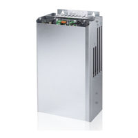
ABB ACS880-604 Hardware Manual (76 pages)
1-phase brake chopper units as modules
Brand:
ABB
| Category:
Food Processor
| Size: 2.61 MB
Table of Contents
Table of Contents
5
1 Introduction to the Manual
9
Contents of this Chapter
9
Safety Instructions
9
Target Audience
9
Contents of the Manual
10
Related Documents
10
Terms and Abbreviations
10
2 Operation Principle and Hardware Description
13
Contents of this Chapter
13
Product Overview
13
Operation Principle
13
Single-Line Diagram of the Drive System
14
Layout Drawing
15
Overview of Power and Control Connections
16
Type Designation Label
17
3 Mechanical Installation
19
Contents of this Chapter
19
Checking the Installation Site
19
Required Tools
19
Installing the Brake Chopper Module
20
Examples: Installing the Brake Chopper Module and a Cooling Fan
21
Example 1: Installation into Generic Closure
21
Example 2: Installation into Rittal TS8 Enclosure
22
Examples: Installing Brake Resistors and a Cooling Fan
23
Example 1: Installation into Generic Enclosure
23
Example 2: Installation into Rittal TS8 Enclosure
24
4 Planning the Electrical Installation
25
Contents of this Chapter
25
Limitation of Liability
25
Generic Guidelines
25
Equipping the Drive with a Main Contactor and Manual Control Switch(Es)
26
Selecting the Brake Circuit Components
28
Calculating the Maximum Braking Power
29
Example 1
29
Example 2
29
Example 3
30
Selecting and Routing the Brake Resistor Cables
30
Minimizing Electromagnetic Interference
30
Maximum Cable Length
30
EMC Compliance of the Complete Installation
30
Placing the Brake Resistors
31
Selecting the Chopper Enable Input Cable
31
Protecting the System against Thermal Overload
31
Operation Principle
31
Protecting the Resistor Cable against Short-Circuits
31
Controlling the Brake Chopper from an External Control Location
32
5 Electrical Installation
33
Contents of this Chapter
33
Safety
33
Checking the Insulation of the Resistor Circuit
34
Selecting the Voltage
34
Synchronizing Multiple Brake Choppers
35
Connecting the DC and Resistor Cables
36
Connection Diagram
36
Connection Procedure
37
Connecting the Thermal Switch
38
6 Installation Checklist
39
Contents of this Chapter
39
Checklist
39
7 Start-Up
41
Contents of this Chapter
41
Start-Up Procedure
41
Preliminary Actions
41
Power Switch-On
42
Operational Checks
42
8 Fault Tracing and Maintenance
43
Contents of this Chapter
43
Maintenance
43
Fault Indications
44
NRED Voltage Reducer Selection for NBRA-669
45
9 Ordering Information
47
Contents of this Chapter
47
Brake Chopper Modules
48
Brake Chopper Cooling Fans
49
Fuses
50
Fuse Bases
51
Brake Resistors
52
Brake Resistor Cooling Fans
53
Attenuator
54
10 Technical Data
55
Contents of this Chapter
55
Ratings
56
Only Chopper
56
Chopper with Standard Resistors
57
Definitions
58
DC Fuses
59
Dimensions, Weights and Free Space Requirements
60
Losses, Cooling Data and Noise
61
Only Chopper
61
Chopper with Standard Resistors
62
Brake Circuit Cable Sizes
63
Brake Chopper Terminal Data
64
Brake Resistor Terminal Data
65
Degree of Protection
65
Auxiliary Circuit Current Consumption
65
CE Marking
66
Compliance with the European Low Voltage Directive
66
Compliance with the European EMC Directive
66
UL Marking
66
More Information on Standards and Markings
66
11 Dimension Drawings
67
Contents of this Chapter
67
Brake Chopper Modules NBRA-658, NBRA-659, NBRA-669
68
Brake Chopper Cooling Fan G2E140-PI51-09
68
Brake Resistors SAFUR180F460, SAFUR125F500, SAFUR200F500, SAFUR210F575
69
Brake Resistor Cooling Fan D4E225-CC01-39
69
12 Example Circuit Diagrams
71
Contents of this Chapter
71
ACS880-604-0640-3 Brake Unit, Master
73
ACS880-604-0640-3 Brake Unit, Follower
74
Further Information
75
Product and Service Inquiries
75
Product Training
75
Providing Feedback on ABB Drives Manuals
75
Document Library on the Internet
75
Advertisement
Related Products
ABB ACS880-607 Series
ABB ACS880-6500-7
ABB ACS880-3770-5
ABB ACS880-0870-7
ABB ACS880-107-0100A-3
ABB ACS880-107-008A0-5
ABB ACS880-107-0025A-5
ABB ACS880-107-0170A-5
ABB ACS880-107-0340A-5
ABB ACS880-107-0042A-7
ABB Categories
Industrial Equipment
Controller
Measuring Instruments
Battery Charger
DC Drives
More ABB Manuals
Login
Sign In
OR
Sign in with Facebook
Sign in with Google
Upload manual
Upload from disk
Upload from URL