Table of Contents
Advertisement
Owner s manual & Installation manual
Bedienungsanleitung und Installationshandbuch
Manuale dell utente e manuale di installazione
Mode d emploi et manuel d installation
Manual de instrucciones y manual de instalación
Bruksanvisning och installationsmanual
使用说明书和安装说明书
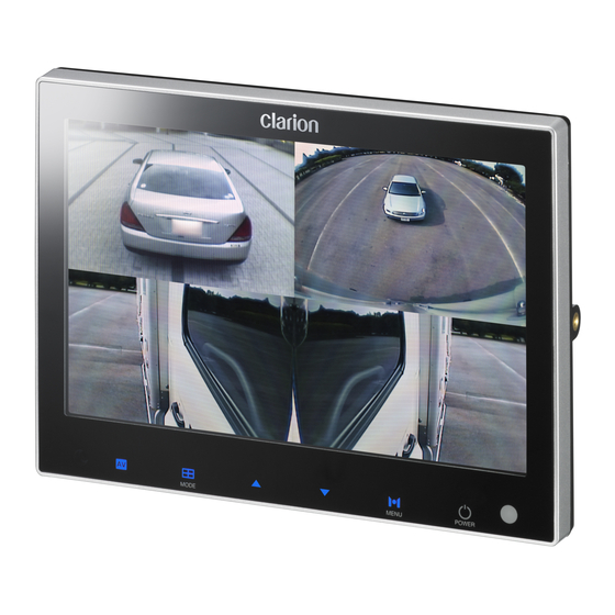
7 WIDESCREEN DIGITAL QUAD COLOR MONITOR
DIGITALER, VIERFACH TEILBARER 7-ZOLL-BREITBILD-FARBMONITOR
MONITOR A COLORI A QUADRANTI DIGITALE WIDESCREEN DA 7
MONITEUR COULEUR NUMÉRIQUE À QUADRI-ÉCRAN DE 7 POUCES
MONITOR EN COLOR CUÁDRUPLE DIGITAL DE PANTALLA ANCHA DE 7
7-TUMS DIGITAL QUAD COLOR BREDSKÄRMSMONITOR
7" 宽屏数字四画面彩色监视器
Advertisement
Table of Contents

Subscribe to Our Youtube Channel
Related Manuals for Clarion CJ-7300G


Summary of Contents for Clarion CJ-7300G
- Page 1 Owner s manual & Installation manual Bedienungsanleitung und Installationshandbuch Manuale dell utente e manuale di installazione Mode d emploi et manuel d installation Manual de instrucciones y manual de instalación Bruksanvisning och installationsmanual 使用说明书和安装说明书 7 WIDESCREEN DIGITAL QUAD COLOR MONITOR DIGITALER, VIERFACH TEILBARER 7-ZOLL-BREITBILD-FARBMONITOR MONITOR A COLORI A QUADRANTI DIGITALE WIDESCREEN DA 7 MONITEUR COULEUR NUMÉRIQUE À...
-
Page 2: Table Of Contents
CONTENTS 1. SAFETY INSTRUCTIONS ....................... 3 2. BEFORE USE ............................. 5 3. FEATURES ............................6 4. CONTENTS ............................6 5. FUNCTION OF EACH PART ....................7 6. FUNCTION ..........................9 [1] POWER ON / STAND-BY ......................9 [2] VOLUME CONTROL ........................ -
Page 3: 1. Safety Instructions
SAFETY INSTRUCTIONS Please read the Safety Rules carefully before using this product. Following the safety rules pre- vents users from damages related with the misuse of the product. It is very important to follow these safety rules. We state Caution and Warning to clarify any potential risk of damage as- sociated with the misuse of the product. - Page 4 CAUTION ● Disconnect battery before installation. Re-connect once installation is complete. Prevents electric shock or short circuit. ● Do not use for long periods without engine running. It may cause battery to go fl at. ● The rear-view monitor image has the same right-left inversion as your vehicle s rearview mirrors.
-
Page 5: 2. Before Use
2. BEFORE USE Precautions (when you use the monitor) ● Use the product at the temperature range of -10° C 60° C. ● Screen may be a little dark when the product is operated in low temperature areas. Screen will show normal luminosity after a few minutes. -
Page 6: 3. Features
3. FEATURES • 7 Widescreen digital TFT LCD with high resolution and low reflection • All functions are displayed on screen (OSD function) • 8 language display Selection (English-French-German-Italy-Spanish-Swedish-Chinese-Japanese) • DC 12 24V • Control via Touch buttons on front panel or via infra-red remote control •... -
Page 7: 5. Function Of Each Part
5. FUNCTION OF EACH PART [Monitor] ① ② ③ ④ ⑤ ⑥ ⑦ ① SENSOR IR-SENSOR for remote control signal ② AV Switch AUX ③ MODE Switch Screen / Select SUB-MENU ④ ▲/▼ Switch camera inputs / Select split mode / Volume control / Set SUB-MENU ⑤... - Page 8 [Remote Controller] ① ② ⑤ ③ ⑥ ④ ⑧ ⑦ ⑨ ⑩ ⑫ ⑪ ① POWER Power ON / Stand-by ② AV Switch AUX ③ OK Select button ④ SUB-MENU setting ◀▶ ⑤ Switch Screen / Select SUB-MENU ▲▼ ⑥ VOL +/- Volume control ⑦...
-
Page 9: 6. Function
6. FUNCTION POWER ON/STAND-BY Press POWER button on remote control or monitor then the picture of the camera will be shown on the monitor. ※ It is set to 4 split mode from the factory. ※ If there is no image, the screen will be BLACK. CAM1 CAM1 image signal received No image signal... -
Page 10: Mute On/Off
MUTE ON/OFF Press MUTE [ ] button on remote control for MUTE function ON/OFF. ※ MUTE function is turned off by operating VOL+/−(Volume control) or POWER button. SWITCH SCREEN : FULL / 2 / 3 / 4 SPLIT Press MODE button on monitor, then the screen switches in the following order. →... -
Page 11: Select Split Mode
SELECT SPLIT MODE Each split screen has two options. In split mode, press ▲/▼ button on the monitor or split screen button on the remote control then the screen switches between both options. 2 SPLIT 3 SPLIT 4 SPLIT SWITCH INPUT VIDEO 1)... - Page 12 2) Switch AUX In camera mode, press AV button on the monitor or remote control then the screen goes di- rectly to AV mode. CAM1 3) Split screen display setting To go to 「Split screen display setting」 , press MENU button on the monitor or SETUP button on the remote control.
-
Page 13: Screen Switch By Trigger Input
SCREEN SWITCH BY TRIGGER INPUT <Trigger input> or <Trigger signal> is when camera priority is selected by a signal, for example if driver uses right/left turn signal or reverse gear, the monitor shows connected camera in driving mode. ※ Below example is based on 「TRG2 (Left turn signal)=CAM2 / TRG3 (Right turn signal)=CAM3 / TRG1 (Reverse gear)=CAM1」... - Page 14 3) When there is the TRG1(Reverse gear) input, CAM1 will be shown as full screen and user can also choose 2 split screen. ※ With this function, you can check the side image simultaneously while reversing. CAM2 CAM1 CAM1 Press ▼ button on the remote control (or ▼...
- Page 15 5) When there is an input signal from more than 2 triggers, the monitor displays fully con- nected screen (Trigger input screen) as the priority order. And the screen switches back when the signal switches off, the rest will be displayed in the priority order. ※...
-
Page 16: 7 . Settings
7 . SETTINGS VIDEO STANDARD SYSTEM, NTSC/PAL SELECTION Using the monitor in PAL format with a NTSC video signal will cause an image malfunction. This product can convert NTSC/PAL format manually but it is not automatic. Before use, please check and set the correct format for your area. NTSC system country : USA, CANADA, JAPAN, KOREA, TAIWAN, MEXICO PAL system country : AUSTRALIA, BELGIUM, CHINA, DENMARK, FINLAND, ATTENTION... -
Page 17: Brightness And Contrast Setting
BRIGHTNESS AND CONTRAST SETTING User can control CONTRAST/BRIGHTNESS/COLOR/TINT. ※ Each menu is set at 50 from the factory. 1) Press SETUP button on the remote control (or PICTURE SETUP MENU button on the monitor) three times, to DIMMER AUTO go into OSD MENU 「PICTURE SETUP」 . CONTRAST 2)... -
Page 18: Initialization
INITIALIZATION ※ Initializes monitor back to factory settings. (Except on Video Standard System, NTSC/PAL) 1) Press SETUP button on the remote control (or PICTURE SETUP MENU button on the monitor) three times to DIMMER AUTO go into OSD MENU [PICTURE SETUP]. CONTRAST 2)... -
Page 19: Camera Mirror/Normal Mode Setting
In such cases, the display location should be set at the closest marker No. • Distance markers cannot be set if non Clarion cameras are used. Caution • The markers may not indicate the exact position of the bumper, the vehicle s width or the distance to the rear. - Page 20 ● MARKER SELECTION ① Press MENU button on the monitor or SETUP button on the remote control four times, and select MARKER SELECT menu. ② Press ▲ / ▼ button on the monitor or ◀/▶ button on the remote control, and switch marker pattern.
-
Page 21: 8. Connections
Camera connecting cable GROUND ACCESSORY(ACC) VIDEO INPUT DC12V/24V *1 Use Clarion Cameras only. * 2 A camera connecting cable, sold sepa- rately, is required for connecting the camera. ■ Please ensure that the correct trigger wires are connected to the corresponding cameras. -
Page 22: 9. Installation
9. INSTALLATION (1) Clean the surface where the stand is to be installed and press stand firmly in place after removing protective tape from stand bottom. (2) Fix the stand with enclosed screws. (3) Assemble the monitor to the stand and adjust it to the correct viewing angle. -
Page 23: 1 0. Troubleshooting
TROUBLESHOOTING Measure Problem Cause No image is displayed. Is camera connected Check the wiring to the camera and the camera properly? connection. Power does not turn on. Is power cable connected Check the wiring. properly? Is a fuse blown out? Replace with a fuse of the same amperage (5A) Color is washed-out. - Page 24 Clarion Co., Ltd. All Rights Reserved. Copyright © 2010: Clarion Co., Ltd. Printed in Korea / Gedruckt in Korea / Stampato nella Corea del Sud / Imprimé en Corée / Impreso en Corea / Tryckt i Korea / 韩国印刷 2010/11...
Need help?
Do you have a question about the CJ-7300G and is the answer not in the manual?
Questions and answers