
Subscribe to Our Youtube Channel
Related Manuals for Clarion CJ-7500E


Summary of Contents for Clarion CJ-7500E
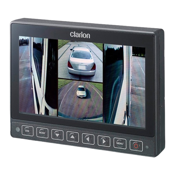
- Page 1 Owner s manual & Installation manual CJ-7500E CJ-7500E 7 WATERPROOF WIDESCREEN DIGITAL QUAD COLOR MONITOR...
-
Page 2: Table Of Contents
■Declaration of conformity Clarion Europe SAS Z.I.du Pré à Varois-Route de Pompey, 54670 We Clarion declares that the product CJ-7500 is Custines, France following the provision of Directive 2004/108/EC telephone: +33(0)3 83 49 44 00... -
Page 3: 1. Safety Instructions
SAFETY INSTRUCTIONS Please read the “Safety Rules” carefully before using this product. Following the safety rules prevents users from damages related with the misuse of the product. It is very important to follow these safety rules. We state “Caution” and “Warning” to clarify any potential risk of damage associated with the mis- use of the product. - Page 4 CAUTION ● Disconnect battery before installation. Re-connect once installation is complete. Prevents electric shock or short circuit. ● Do not use for long periods without engine running. It may cause battery to go fl at. ● The rear-view monitor image has the same right-left inversion as your vehicle s rearview mirrors.
-
Page 5: 2. Before Use
BEFORE USE 2. Precautions (when you use the monitor) ● Use the product at the temperature range of -10 ℃ ℃ ● Screen may be a little dark when the product is operated in low temperature areas. Screen will show normal luminosity after a few minutes. -
Page 6: 3. Features
FEATURES 3. ・ 7 WVGA (800x480) LCD panel ・ Water resistant (IP67), Aluminum housing ・ 8 language display selection (English-French-German-Italian-Spanish-Swedish-Chinese-Japanese) ・ DC12∼24V ・ Max.4 camera input ・ Camera input screen inversion (Normal/Mirror mode) ・ User can choose split screen (2/3/4 Split screen) ・... -
Page 7: 5. Button Functions
BUTTON FUNCTIONS 5. [Monitor] ① ② ③ ④ ⑤ ⑥ 1. DIMMER SENSOR Automatic brightness control sensor 2. DIM DIMMER 3. MODE Switch Screen / Select SUB-MENU DOWN/UP/LEFT/RIGHT 5. MENU Switch Main Menu 6. POWER Power ON/Stand-by... -
Page 8: 6. Functions
FUNCTIONS 6. POWER ON/OFF CAM1 CAM4 Press [ ] button then the picture from the cameras will be shown on the monitor. Press [ ] button again to switch off. CAM2 CAM3 * If there is no camera video input, the screen will remain Black. * Factory default setting shows 4 way split screen. -
Page 9: Select Split Mode
SELECT SPLIT MODE Each split screen has two options. In split mode, press [ ] button then the screen switches between both options. 2 split screen 3 split screen 4 split screen 2 split screen 3 split screen 4 split screen CAMERA SELECTION 1) FULL SCREEN MODE In full screen mode, press [... -
Page 10: Camera Selection
2) 2 SPLIT SCREEN MODE Press [MENU] button to go to 「SPLIT SCREEN SETUP」 . CAM2 SELECT INPUT SPLIT SCREEN SETUP CAM 1 SET LEFT CAM 2 SET RIGHT CAM 3 CAM 4 Please select the camera position (left Then press [ ] button to go to Then press [ ] button to save... -
Page 11: Camera Mirror/Normal Mode Setting
CAMERA MIRROR/NORMAL MODE SETTING 1) CAM1 full screen MIRROR SET CAM1 MARKER SETUP CAM1 MIRROR CAM2 MIRROR CAM3 NORMAL CAM4 MIRROR Press [MENU] button. Press [MENU] button. Select camera with [ ] button and then press [ ] button to select Normal / Mirror view. - Page 12 In such cases, the display location should be set at the closest marker No. • Distance markers cannot be set if non Clarion cameras are used. Caution •...
- Page 13 2) MARKER ADJUSTMENT (Adjusting the bumper position) - Press [MENU] button five times, and select MARKER ADJUST menu. - Press [ ] button, and select H / V. (H: horizontal / V: vertical ) - Press [ ] button, and switch marker pattern. (H = -12 ~ +12, V = -12 ~ +12, Default setting: H = 0, V = 0) - After 10 seconds, set up screen disappears, and set up finishes.
- Page 14 2) In case of TRG2 (Left turn signal) or TRG3 (Right turn signal), you can choose full screen or split screen by OSD setting. * This function is for showing not only Left(Right) but also rear view together at the same time, regardless of former screen status.
- Page 15 4) In case of a hazard flasher trigger(TRG2+TRG3), the monitor displays CAM1~CAM4 as quad split screen. The screen switches back when the hazard flasher trigger is switched off. CAM1 CAM2 CAM1 CAM4 CAM2 CAM3 The example is set with TRG1(Reverse gear)=CAM1 / TRG2(Left turn signal)=CAM2 / TRG3(Right turn signal)=CAM3 NOTICE 5) When more than two trigger signals are received at once, the monitor will display the highest priority trigger.
-
Page 16: On Screen Distance Marker Setting
TINT LANGUAGE ENGLISH VIDEO SYSTEM NTSC RESET ▶ Please select NTSC for video system as Clarion cameras are compatible with NTSC video system. NOTICE DIMMER SENSOR SETTING 1) Press [MENU] button until OSD menu [PICTURE SETUP] PICTURE SETUP appears. DIMMER... -
Page 17: Language Setting
LANGUAGE SETTING 1) Press [MENU] button until OSD menu [PICTURE SETUP] PICTURE SETUP appears. DIMMER AUTO 2) Press [ ] button to move to language and choose CONTRAST proper value by pressing [ ] button. BRIGHTNESS COLOR TINT LANGUAGE ENGLISH VIDEO SYSTEM NTSC RESET... -
Page 18: 8. Installation
INSTALLATION 8. INSTALLATION (U-Bracket) Double side adhesive tape Standard Installation 1. Please ensure that the monitor is installed with enough room for heat to dissipate. Install the monitor stand with enclosed screws and double side adhesive tape as per the picture. 2. -
Page 19: 9. Connections
DC12V/24V *1 *2 Camera connecting cable *1 Use Clarion Cameras only. * 2 A camera connecting cable, sold separately, is required for connecting the camera. ■ Please ensure that the correct trigger wires are connected to the corresponding cameras. Standby + (for rear-view) ORANGE (CAM1, priority) * Connect this cable to the + side of the Reverse gear globe. -
Page 20: 10. Troubleshooting
TROUBLESHOOTING Problem Cause Measure No image is displayed. Is camera connected Check the wiring to the camera and the camera properly? connection. Power does not turn on. Is power cable connected Check the wiring. properly? Is a fuse blown out? Replace with a fuse of the same amperage (5A) Color is washed-out. - Page 21 MEMO...
- Page 22 MEMO...
- Page 23 MEMO...
- Page 24 Clarion Co., Ltd. All Rights Reserved. Copyright © 2013: Clarion Co., Ltd. Printed in Korea 2013/12 CJ-7500E...
Need help?
Do you have a question about the CJ-7500E and is the answer not in the manual?
Questions and answers