
Subscribe to Our Youtube Channel
Related Manuals for Citizen OP900II


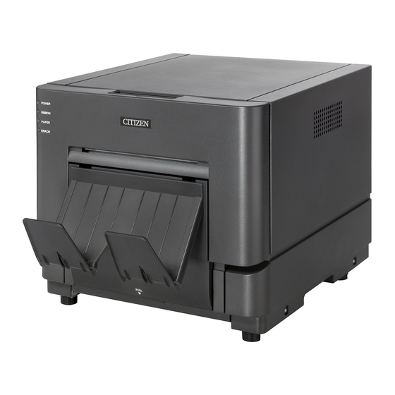
Summary of Contents for Citizen OP900II
-
Page 1: Technical Manual
Technical Manual OP900II Version 1.00... - Page 2 ● Concerning Copyright The copyrights for this Technical Manual are the property of Dai Nippon Printing Co.,Ltd. Reproduction of any or all of the contents of this document without consent of the company is a violation of copy-right law. ● Concerning Safety Warnings Warnings regarding safety and use, as well as the contents of the Technical Manual, conform to standards existing as of the date published.
-
Page 3: Introduction
Introduction Thank you for purchasing this printer. This document explains how to handle and operate the Photo Printer. Please read this manual before using the printer. Especially important is reading the “For Safe Use” section (pg 2-4) to insure proper use. Please refer to the user's manual for the setup of the printer. - Page 4 Warning Do not use with other than the designated voltage and frequency. Doing so could cause ・ electric shock or fire. Do not overstress outlets with too many power cords or plugs. The outlet could overheat ・ and cause a fire. Do not damage, cut, alter, or bundle the power cords.
- Page 5 Caution ・ Do not put in places with excessive humidity or dust. It could result in fire, electric shock, or malfunction. ・ Do not set in an unstable location. The printer could fall and cause injury to the customer or other people.
-
Page 6: General Warnings
General Warnings ・ Before using this printer, please read “For Safe Use”, and follow the instructions listed therein. ・ Be careful not to drop paperclips, pins, etc, into the printer, as they could cause malfunctions or damage. ・ Use care when moving or setting up the printer. Dropping it could cause injury or damage to other property. -
Page 7: Table Of Contents
Contents Introduction ......................................2 For Safe Use ......................................2 General Warnings....................................5 Chapter 1 Cleaning ..............................8 Alcohol that can be used for cleaning ..............................8 Cleaning the Platen Roller..................................8 Cleaning the Grip Roller and Pinch Roller............................9 Cleaning the thermal head .................................. 10 Chapter 2 Disassembly・Reassembly ......................... - Page 8 6, Disassemble・Assemble( Mechanical frame R Assy)......................33 Replacement Procedure 6-10 GEAR_DUMPER ................... 34 Replacement Procedure 6-11 GEAR_HEAD_PINCH_CAM_R ............34 Replacement Procedure 6-30 STEP_MOTOR_MAIN_LC ..............34 Replacement Procedure 6-12 Bearing(d6-D12)..................34 Replacement Procedure 6-13 Holder_Ribbon_RFID ................34 Replacement Procedure 6-29 Holder_Ribbon_Supply_R..............34 Chapter 3 Using OP2-Tools ............................
-
Page 9: Chapter 1 Cleaning
Alcohol that can be used for cleaning ・Ethyl alcohol (reagent ethanol grade 1, absolute ethanol, etc.) (99.5v/v%) 2-propanol (IPA, isopropyl alcohol) (99.5v/v%) ・ Caution ・ Except for the specified alcohol cleaners, do not use other agents such as benzene, thinners, etc. -
Page 10: Cleaning The Grip Roller And Pinch Roller
Cleaning the Grip Roller and Pinch Roller Caution ・Before performing maintenance, turn the power OFF, and unplug the power and USB cables. 【Advance preparation】Create of cleaning sheet. Create a sheet of paper with double-sided tape on it (on the back of the sheet when printer is initialized). Paper(Back)... -
Page 11: Cleaning The Thermal Head
4, Lifting the media forward so the double-sided tape doesn't tough the platen roller,turn the grip roller in the direction of the arrow and advance the paper. While lifting the Turn the grip bottom of the roller pulley. paper and pulling towards you ・・・, 5, When paper was advanced from edge a little forward, return the head cam to its original position, and close the mecha cover R to finish the process. -
Page 12: Chapter 2 Disassembly・Reassembly
・ ・ Caution Before disassembly, turn the power OFF, and unplug the power cord and USB cable. There are sharp edges in the printer when the cover is removed, and the user comes to touch this place. When disassembling and assembling, wear gloves, and use care not to get cut. Return the head cam to its original position, and close the mecha cover R to finish the process. -
Page 13: Maintenance Parts
Maintenance parts ◆PC (OS: Windows 7,VISTA,XP), USB2.0, Need more than 512MB memory ◆Tool Torque screw driver (0.25~1.2N・m) +screw driver No.0 , + screw driver No.1 , + screw driver No.2 - small screw driver , - large screw driver Screw driver for adjustment (Will use it for adjustment of variable resistance) Nipper , Longnose pliers , Spring tool... -
Page 14: 1, Disassembly, Assembly (Outer Cover)
1, Disassembly, Assembly (Outer cover) Hook Hook Hook Part Name Caution regarding Disassembly and Assembly 1-30 SCRAP_BOX 1-27 CASE_FRONT 2 screws. Upper hook.(Open the inside hook of 2 places, and lift it from the under.) 1-25 Case_side_R 3 screws(Remove the front hook of 1 place ,and lift it.) 1-24 Case_side_L 3 screws(Remove the front hook of 1 place ,and lift it.)... -
Page 15: 2, Disassembly・Assembly(Printer Mechanism
2, Disassembly・assembly(Printer mechanism) Most parts can be exchanged by removing outer cover 2-29 Head Frame Assembly 3-40 Fan Motor 2-32 Thermal Print Head Assembly 3-32 Power Supply Unit 4-33 ROLLER_PLATEN 2-33 RFID PCB Assembly 4-32 ROLLER_PINCH 4-71 ROLLER_GRIP 4-22 Pulley,Grip Roller 4-9 BELT_TIMING 6-11 GEAR_HEAD_PINCH_CAM_R 4-53 GEAR_HEAD_PINCH_IDLE... -
Page 16: Replacement Procedure 2-32 Thermal Print Head Assembly
Replacement Procedure 2-32 Thermal Print Head Assembly ① Remove 2-19 ,Remove 2-2 ② Remove Connector 10 pin FFC 28pin(470mm), 22pin(505mm) Note)Be sure to unlock the connector when inserting and removing the FFC.FFC is fixed with the double-side tape. screws) Remove 2-32 Thermal Print Head Assembly ③Remove ④Replace 2-32 Thermal Print Head Assembly... - Page 17 Notes when attaching the thermal print head When attaching, make sure the print head is pressed firmly against the heatsink. No gap Not good Head installation ③Fold down the FFC ①Put the point of FFC. ②Fix the other side with along the edge .
-
Page 18: Replacement Procedure Mecha Assy
Replacement Procedure Mecha Assy ①Spring of 2 places 2-5(Small) and 2-4(Large). Note)When the spring is removed, the Mecha Assy could drop. Use caution. ②3 connectors, Plug out Harness from 2-25 Locking Clamp (refer to the figure below) ③2-1, 2-27 with right and left each screw (Lubricate the point of shaft when replacing . ) 2-21 Ground 1 screw M4 ④Remove the Mecha Assy Note) When replacing, the various adjustments must be performed. -
Page 19: Replacement Procedure 2-29 Head Frame Assembly
Replacement Procedure 2-29 Head Frame Assembly ①connectors(refer to the figure below) ②2-3 PLATE_HEAD_Holder 2 screws ③2-7 Spring Note) When the spring is removed, the Mecha Assy could drop. Use caution. ④Slide the Head Assy right and lift it up. Note)Note) Be careful of the Ribbon Rewind Assy gear when sliding it. Note) ) When replacing, the various adjustments must be performed (refer to Ch.4) Front... -
Page 20: Replacement Procedure 2-30 Ribbon Winding Assy
Replacement Procedure 2-30 Ribbon Winding Assy ①Connector of one place (refer to Wiring Diagram 2) ②2-6 Springs ③E Ring 1 place ④2-3 PLATE_HEAD_Holder 2 screws ⑤Slide the Head Assy to the right. ⑥Remove the 2-30 Ribbon Winding Assy while rotating. Note)Rotating metal parts that are in contact should be lubricated. - Page 21 Thermal Print Head Assembly 28pin(470mm) 26pin(505mm) RFID PCB Assembly 7pin(500mm) LED PCB ASSY Wiring Diagram 2 FFC 26pin FFC 28pin Mecha Assy Head Ribbon Rewind Assy 14pin Assy 5pin 12pin 10pin 6pin Wiring Diagram 3 2-18 FFC 7pin RFID PCB Assembly 7pin Put the double-side tape.
-
Page 22: 3, Disassembly・Assembly(Frame Assy
3, Disassembly・Assembly(Frame Assy) Caution When exchange Power Supply Unit Even after the power is turned OFF, there are high voltage parts inside. Do not disassemble for 10 minutes after the power is turned OFF. Replacement Procedure DAMPER ①3-15 Gear_open Note)The Gear_open is not fixed. Please note the drop and the loss. ②3-1 2 screws ③3-6 Pull the 3-5 Straight Pin out of the 3-6 Shaft Note) Lubricate the metal contact parts of 3-6 Shaft... -
Page 23: 4, Disassembly, Assembly(Mechanical Assy
4, Disassembly, Assembly(Mechanical Assy) Replacement Procedure 4-68 Auto Cutter Unit ①4-60 Wiring Harness 4pin(refer to the figure below) ②2-12 2pin(the figure below) ③Remove from the printer in the screw 2 locations. ④Remove the 4-681 in the screw 2 locations. Note) You need to adjust the print position and cut position. (refer to Ch.4) Replacement Procedure 4-9 BELT_TIMING Loosen the 4-50 PLATE_TENSIONER screw. -
Page 24: Replacement Procedure 4-71 Roller_Grip
Replacement Procedure 4-71 ROLLER_GRIP ①Disengage the outer side of the 4-7 SPRING_PINCH in 2 places, left and right Note) This is a powerful spring. Use caution to avoid injury. ②Remove the E Ring of 2 places.(4-46, 6-26)Next, remove the 4-26 Bush.3B and the 6-1 Plate_Pinch_Up_R. ③Remove the 4-44 E Ring. -
Page 25: Replacement Procedure 4-32 Roller_Pinch
Replacement Procedure 4-32 ROLLER_PINCH ①Remove the 4-71 ROLLER_GRIP. ②Remove the 4-46 E Ring and the 4-26 Bush. ③Remove the 6-1 Plate_Pinch_Up_R with E Ring. ④Remove the 4-32 ROLLER_PINCH and 4-30 Bearing (d6-D12 F). Note) By removing 5-4 and 6-1, the ROLLER could drop, so beware of injury or damage. Mecha Flame L Assy Mecha Flame R Assy... -
Page 26: Replacement Procedure 4-53 Gear_Head_Pinch_Idle
Replacement Procedure 4-53 GEAR_HEAD_PINCH_IDLE R Side ①Remove the 4-9 BELT_TIMING, the 4-51 ROLLER_TENTIONER, and the 4-22 Pulley, Grip Roller. ②Remove the 4-45 E Ring L Side ①Remove the 2-12 PCB MECHA SENSOR Assembly. ②Remove the 5-7 Guide_Cable. ③Remove the 4-45 E Ring. Note)By removing 4-53 GEAR_HEAD_PINCH_IDLE , 4-10 Straight Pin can drop. -
Page 27: Replacement Procedure 4-55 Gear_Roll_Reduction_3
Replacement Procedure 4-55 GEAR_ROLL_REDUCTION_3 4-55 GEAR_ROLL_REDUCTION_3 is assembled with the hook. Note) Putting too much force on the hook can damage it. Replacement Procedure 4-57 Gear,Cassette 4-45 E Ring Replacement Procedure 4-56 Torque Limiter It can be removed by removing 4-57 Gear, Cassette Note) 4-52 Straight Pin can drop. -
Page 28: Replacement Procedure 4-63 Humidity Sensor Module
Replacement Procedure 4-63 Humidity Sensor Module Remove the connector. 5-22 HOLDER_PAPER_L is assembled with the hook. It can be removed by removing hook. Note) Putting too much force on the hook can damage it. Replacement Procedure 4-64 Paper Sensor PCB ①Connector 1 place ( refer to Wiring Diagram 6) ②4-23 cover_cable is assembled with the hook. -
Page 29: Replacement Procedure 4-66Paper Guide Assy
Replacement Procedure 4-66Paper Guide Assy(It is necessary to resolve mecha Assy to remove these parts) 4-68 Auto Cutter Unit 2-12 PCB MECHA SENSOR Assembly 4-8 spring_paper_holder_LC Each roller or shaft at 4-33, 4-71, 4-15, 4-32, 4-14, 4-12, 4-13 4-53 GEAR_HEAD_PINCH_IDLE 4-5 Spring_Mecha_Open 4-23 cover_cable Please remove the parts respectively. -
Page 30: Replacement Procedure 4-65 Sensor Plate Assy
Replacement Procedure 4-65 Sensor Plate Assy(It is necessary to resolve mecha Assy to remove these parts) 4-68 Auto Cutter Unit 2-12 PCB MECHA SENSOR Assembly 4-8 spring_paper_holder_LC Each roller or shaft at 4-33, 4-71, 4-15, 4-32, 4-14, 4-12, 4-13 4-53 GEAR_HEAD_PINCH_IDLE 4-5 Spring_Mecha_Open 4-23 cover_cable Please remove the parts respectively. - Page 31 Wiring Diagram 5 4-68 Auto Cutter Unit 4pin STEP_MOTOR_MAIN_LC 6pin 4-60 Wiring Harness 4pin → 4-68 6pin → 6-21 12pin→ 2-10 Wiring Diagram 6 4-68 Auto Cutter Unit 2pin 4-61 Wiring Harness 14pin → 2-10 4-64 Paper Sensor PCB 4-62 Wiring Harness 2pin 4pin →...
-
Page 32: 5, Disassemble・Assemble(Mechanical Frame L Assy
5, Disassemble・Assemble(Mechanical frame L Assy) Inside of cam... -
Page 33: Replacement Procedure Assembly,Drum_Supply_Ribbon
Replacement Procedure Assembly,DRUM_Supply_Ribbon 1-22 COVER_MECHA_L 5-11 Spring_ribbon_Guide 5-28 E Ring 1 place Note)Ribbon supply tension adjustments must be performed. (refer to Ch.4) Replacement Procedure 5-15 GEAR_HEAD_PINCH_CAM_L 1-22 COVER_MECHA_L Disengage the outer side of the 4-7 SPRING_PINCH in 2 places, left and right. 2-12 PCB MECHA SENSOR Assembly 5-28 E Ring 1 place. -
Page 34: 6, Disassemble・Assemble( Mechanical Frame R Assy
6, Disassemble・Assemble( Mechanical frame R Assy) カム内側... -
Page 35: Replacement Procedure 6-10 Gear_Dumper
Replacement Procedure 6-10 GEAR_DUMPER Disassembly mechanical Assy 2 screws. Replacement Procedure 6-11 GEAR_HEAD_PINCH_CAM_R 1-23 COVER_MECHA_R E Ring 1 place. Note) Be sure to lubricate gears and cams. During assembly 5-15 GEAR_HEAD_PINCH_CAM_L and 6-11 GEAR_HEAD_PINCH_CAM_R CAM-configuration must be matched on left and right sides. If they are not matched, it won't operate properly. -
Page 36: Chapter 3 Using Op2-Tools
1.Installing and Running OP2-Tools 1-1. Installation (1) Check that the Printer Driver “OP900II” is installed in the computer. From the “START” menu, select “Printer and Fax”, and check that “OP900II” is installed there. ※ If the Printer Driver is not there, you need to install the Driver. - Page 37 (1) Connect the printer and the computer, and check that the printer is turned ON. (2) Run “OP2-Tools32.exe”(32bit OS) or “OP2-Tools64.exe”(64bit OS). (3) If multiple printers installed on the computer, the "Please select printer" window will appear. Select “OP900II” here. (4) The following window will open, and “OP2-Tools” will start.
-
Page 38: Using Op2-Tools
Open This is not used. Selects the printer. Port setting (Selection is possible when multiple printers are connected.) Exit Closes OP2-Tools. Port setting If multiple printers installed on the computer, the "Please select printer" window will appear. Select “OP900II” here. - Page 39 2-2. Control Data Display Function Write All Data…(*.CWD) Writes color control data to the printer. CWD Version Check Displays the printer’s color control data version. (1) Write All Data…(*.CWD) This writes the color control data to the printer. The file selection dialog box will open. Select the CWD Control data to be rewritten, and click on “Open”.
- Page 40 2-3. Status Display Function Printer Status Displays the current printer status. ROM Version Displays the printer’s firmware version. Displays the current ribbon status. Counter (quantity remaining), Ribbon Status Lot No, Offset value (RFID Tag data) Print Sheets Counter Displays the printer’s current life counter. (1) Printer Status To display the printer’s current status, click on “Get”.
- Page 41 (3) Ribbon Status To display the current ribbon status, click on “Get”. (4) Print Sheets Counter To display the Life counter, Counter A/B, and Matte Counter, Counter M, click on “Get”. To clear the Counter A/B, click on “Clear A” or “Clear B”. To clear the Counter M, click on “Clear M”.
- Page 42 2-4. Option Display Function Setup of Media Not used Setup of HeadRank Displays and writes the head rank. Setup of HeatRank Displays and writes the heat rank. Driver Adjustment Displays and writes the driver adjustment. Setup of Printer Serial No Displays and writes the serial number.
- Page 43 (2) Setup of HeatRank To display the Heat Rank, click on “Get”. Enter the value from the revision label inside the printer and click “Setup” to write. (3) Driver Adjustment To display the Driver Adjustment values, click on “Get”. Enter the Driver Adjustment value stuck on the driver board, and click on "Setup". The adjustment value will be written to the printer.
- Page 44 (5) Mechanism Adjustment To display the current print position and cut scrap length adjustment values, click on “Get”. ① Cutting position adjustment This adjusts the cut scrap length for the first print. Print one all-gray sheet. Then measure the cut scrap length from it. Enter the adjustment value and click on “Setup”.
- Page 45 ② Print position adjustment This adjusts the length of the remaining printed area on the print scrap (post-printing) from the second and later prints. Print 2 successive all-gray sheets. Then measure the remaining print length. Enter the adjustment value and click on “Setup”. The adjustment value will be written to the printer.
- Page 46 (6) Sensor Monitor To display the current printer voltage, temperature, and humidity of the internal sensors, click on “Start”. (7) Flash rom writer This writes the firmware to the printer. The file selection dialog box will open. Select the ROM data to be rewritten, and click on “Open”.
- Page 47 2-4. Window Display Function Cascade Lines up the open Windows. 2-5. Help Display Function About Displays the OP2-Tools version.
-
Page 48: Chapter 4 Adjustment Settings
Post-Reassembly Adjustment and Confirmation Items After replacing parts and Assembly., the adjustments and confirmations necessary are shown below. Replacement Cutter Ribbon Power Unit Main PCB Driver board Head Each sensor Assembly tension unit Adjustment Head power voltage ○ Sensor voltage ○... -
Page 49: Head Power Voltage Adjustment
1,Head Power Voltage Adjustment ① This adjusts the Head Power Voltage. Turn the printer ON. Caution The Power Unit has high voltage, and can get hot, so use caution. ② Adjust using the variable resistor while monitoring Power Unit CN101 with a meter. Head Power Voltage Range 35.0V ±0.05V +... - Page 50 Measuring the Sensor Voltage using OP2-Tools. ① Turn the printer ON. ② Run OP2-Tools. ③ Select the printer for Sensor Voltage Adjustment. ④ Under the “Option” menu, click on “Sensor Monitor”. ⑤ “Sensor monitor” will appear. Click on “Start” to start measuring. Adjustment ranges When adjusting When checking operation...
- Page 51 (1)Adjusting Paper Sensor System Perform the Paper Detection Sensor (VR1, VR3) adjustments as follows. ① Turn the printer ON. ② Run OP2-Tools, and select the printer to be adjusted. ③ Run the OP2-Tools Sensor Monitor, and begin measuring. ④ Adjust each sensor. (Ex)Adjusting Paper End Sensor(VR1)...
- Page 52 (2)Adjusting the Ribbon Sensors Monitor the Ribbon Sensor R, C (VR2, VR4) as follows. ① Turn the printer ON. ② Run OP2-Tools and select the printer to be adjusted. ③ Run the OP2-Tools Sensor Monitor, and begin measuring. ④ Set the ribbon so that the Cyan area is over the sensor. ※ Use an unused section of ribbon. Ribbon sensor ⑤...
-
Page 53: Mechanism Adjustments
3,Mechanism Adjustments Adjusting cut scrap length and print position ※These adjustments are made to compensate for mechanical deviances (cutter, sensor). ① Run OP2-Tools. ② Under the “Option” menu, click on “Mechanism Adjustment”. ※Before starting adjustments, set the cutting position and print position values at 0.0 ㎜. Procedure 1. - Page 54 Procedure 2. After adjusting the scrap length, measure the printed area length remaining in the scrap from the 2 print, and adjust the print position. Adjusting the print position will not affect the cut scrap length. Print result Reason Adjustment Printed area in scrap Distance from sensor to head is Set the Print position adjustment...
-
Page 55: Thermal Print Head Settings
4,Thermal Print Head Settings (1) Setting “Head Rank” ① Check the Thermal Print Head resistance value. ② Turn the printer ON. ③ Run OP2-Tools and select the printer to be set. ④ Under the “Option” menu, click on “Setup of HeadRank”. ⑤... -
Page 56: Driver Board Setting
5,Driver board setting When Replacing the Main Board or the Driver Board. ① When replacing the Driver Board, check the value on the seal of the driver board. When replacing the Main Board, check the value on the revision seal or the driver board. ②... -
Page 57: Checking And Setting The Serial Number
6,Checking and Setting the Serial Number When Replacing the Main Board ① Before replacing the Main Board, get the value and write it down, or check the rating plate. ② Turn the printer ON. ③ Run OP2-Tools and select the printer to be set. ④... -
Page 58: Rewriting Firmware And Cwd Control Data
7,Rewriting Firmware and CWD Control Data 【Note】While rewriting firmware and CWD control data (when the green LED is blinking), do not turn the printer OFF or unplug the USB cable (1) Rewriting Firmware ① Turn the printer ON. ② Run OP2-Tools, and select the printer for firmware rewriting. ③... - Page 59 (2) Rewriting CWD Control Data ① Turn the printer ON. ② Run OP2-Tools, and select the printer for CWD control data rewriting. ③ Under the “Control Data” menu, click on “Write All data”. ④ The file selection window will open. Select the CWD control data for rewriting, and click on the “Open”...
-
Page 60: Adjusting The Ribbon Feed Tension
8,Adjusting the Ribbon Feed Tension 【Advance preparation】Ready the tension measuring ribbon. Make a ribbon with the diameter φ20.7 for the supply side. Fold the paper in half, open the tension gauge hole, and affix it with double-sided tape. Diameter φ20.7 ribbon (This can be made easily by rolling back 6 frames on a finished ribbon roll) ①... -
Page 61: Chapter 5 Trouble Shooting
1, Check the printer status with the printer LED display If there is an error, first check the printer status with the LED display LED Display Paper end Ribbon end Cover open and Cover open Display paper none. Power ● ●... -
Page 62: 2, Check The Printer Status From Pc
2, Check the printer status from PC. If the LED display of the printer is an error, get the printer status with OP2-Tools, and check the type of error. (1)Getting the Printer Status ① Run OP2-Tools. In the “Status” menu, click on “Printer Status”. ②... -
Page 63: 3, Error Causes And Solution
3, Error Causes and Solution Try to determine the cause of the error from the error display and actual problem, and rectify it. Paper End Event Cause and Solution Reference Paper end Replace the paper User’s Manual (Usually operation) There is still media Faulty of sensor adjustment. -
Page 64: Ribbon End
Ribbon End Event Cause and Solution Reference Ribbon end Replace the ribbon. User’s Manual (Usually operation) Faulty the ribbon rewind Ribbon rewind encoder is not functioning. Ch.2 2-30 mechanism. → Faulty sensor board or harness. RFID cannot be read. Faulty RFID board or FFC Ch.2 2-33, 2-18 Ribbon Error )... -
Page 65: Ribbon Tension Error
Ribbon Tension Error Event Cause and Solution Reference Ribbon feed tension is Damaged Ribbon supply Assy. Ch.2 5-3 incorrect. → Replace ribbon supply Assy. Damaged ribbon supply Assy motor. Faulty harness. Ch.2 5-25, 4-59 → Replace the motor or the harness. Incorrect harness connection, or it is damaged. -
Page 66: Illegal Head Temperature
Illegal Head Temperature Event Cause and Solution Reference The media temperature Incorrect harness connection. cannot be detected. Harness Diagram Faulty thermal print head. → Replace Ch.2 2-32 Thermal printer head. ⇔ Damage of Harness or FFC Ch.2 2-15, 2-29 Faulty main board. → Replace Ch.2 2-35 Power Supply Fan Stopped Event... -
Page 67: Rfid Module Error
RFID Module Error Event Cause and Solution Reference RFID cannot be read. Incorrect harness connection. Harness Diagram Faulty harness. → Replace Ch.2 2-18 Faulty RFID board. → Replace Ch.2 2-33 Faulty main board. → Replace Ch.2 2-35 Paper Definition Error Event Cause and Solution Reference... -
Page 68: 4、Movement Flow
4、Movement Flow Ribbon Head Paper edge sensor Pinch Roller Down Pinch Roller Pinch Roller (PC mark sensor) Feed Ribbon (rewind) Paper edge detection Paper Feed Ribbon sensor Yellow Ribbon Mark detection Head Down Print Head Up Feed Magenta Cyan Cutter Feed Margin Cut Feed... -
Page 69: Causes And Solution (Print Quality)
5、Causes and Solution (Print quality) Error type Cause Solution Ribbon sticking Improper voltage for the ribbon Adjust the sensor voltage using TOOLS position detection sensor White margin (top or Improper mechanism adjustment Adjust mechanism using bottom) TOOLS White margin (left or Problem with the setting Reset the paper right) -
Page 70: Chapter 6 Appendix
Information on servicing the printer For questions regarding operation and servicing of the printer, contact the dealer where the printer was purchased. - Page 71 Cable THERMAL HEAD Connection 35VGND 35VGND 35VGND 35VGND 35VGND HeadUpDownMotor Head UpDown1 Motor Head UpDown2 Motor 3.3VGND Ribbon Step1A Motor Tension HP sensor Ribbon Step1B Motor Paper end sensor Ribbon Step2A Motor RibbonStepMotor 3.3VGND Ribbon Step2B Motor Cutter SEN1 Head position2 SEN Head position1 SEN Ribbon edg sensor right Main Step_B# Motor...
Need help?
Do you have a question about the OP900II and is the answer not in the manual?
Questions and answers