Table of Contents
Advertisement
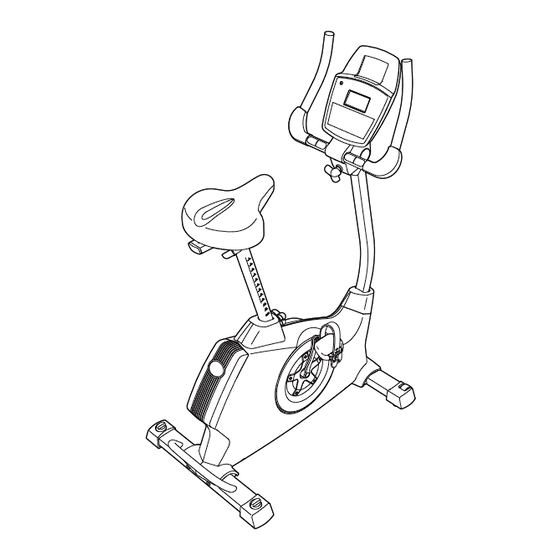
Model No. NTEVEX73910.0
Serial No.
Write the serial number in the
space above for future reference.
Serial Number
Decal (under frame)
QUESTIONS?
If you have questions, or if there are
missing parts, please contact us:
Call: 08457 089 009
From Ireland: 053 92 36102
Website: www.iconsupport.eu
Write:
ICON Health & Fitness, Ltd.
c/o HI Group PLC
Express Way
Whitwood, West Yorkshire
WF10 5QJ
UK
CAUTION
Read all precautions and instruc-
tions in this manual before using
this equipment. Keep this manual
for future reference.
USER'S MANUAL
www.iconeurope.com
Advertisement
Table of Contents

Related Manuals for NordicTrack GX 3.0 NTEVEX73910.0


Summary of Contents for NordicTrack GX 3.0 NTEVEX73910.0
- Page 1 USER'S MANUAL Model No. NTEVEX73910.0 Serial No. Write the serial number in the space above for future reference. Serial Number Decal (under frame) QUESTIONS? If you have questions, or if there are missing parts, please contact us: Call: 08457 089 009 From Ireland: 053 92 36102 Website: www.iconsupport.eu Write:...
-
Page 2: Table Of Contents
If a decal is missing or illegible, see the front cover of this manual and request a free replacement decal. Apply the decal in the location shown. Note: The decal(s) may not be shown at actual size. NordicTrack is a registered trademark of ICON IP, Inc. -
Page 3: Important Precautions
IMPORTANT PRECAUTIONS WARNING: To reduce the risk of serious injury, read all important precautions and instructions in this manual and all warnings on your exercise bike before using your exercise bike. ICON assumes no responsibility for personal injury or property damage sustained by or through the use of this product. -
Page 4: Before You Begin
BEFORE YOU BEGIN Thank you for selecting the revolutionary NordicTrack after reading this manual, please see the front cover ® GX 3.0 exercise bike. Cycling is an effective exercise of this manual. To help us assist you, note the product... -
Page 5: Assembly
ASSEMBLY Assembly requires two persons. Place all parts of the exercise bike in a cleared area and remove the packing materials. Do not dispose of the packing materials until assembly is completed. In addition to the included tool(s), assembly requires a Phillips screwdriver , an adjustable wrench , and a rubber mallet... - Page 6 To make assembly easier, read the information on page 5 before you begin. Attach the Rear Stabilizer (3) to the Frame (1) with two M10 x 95mm Patch Screws (76). 2. Attach the Front Stabilizer (2) to the Frame (1) with two M10 x 95mm Patch Screws (76).
- Page 7 3. Loosen the Adjustment Knob (27) in the Frame (1) a few turns. Orient the Seat Post (6) as shown. Then, pull the Adjustment Knob (27) outward and insert Adjustment the Seat Post into the Frame (1). Holes Slide the Seat Post (6) upward or downward to the desired position, and release the Adjustment Knob (27).
- Page 8 5. Apply some of the included grease to the barrel of an M6 x 70mm Bolt Set (50). Orient the Handlebar (5) and the Upright (4) as shown. While a second person holds the Handlebar (5) near the Upright (4), insert the Extension Wire (59) upward through the Handlebar.
- Page 9 7. Orient the Upright (4) assembly and the Pivot Cover (12) as shown. Slide the Pivot Cover (12) upward to the Handlebar (5). Tip: Bend and flex the Pivot Cover slightly to slide it over the Handlebar. Attach the Pivot Cover (12) to the Handlebar (5) with four M4 x 16mm Screws (90).
- Page 10 8. Slide the Front Shield Cover (7) upward onto the Upright (4). While another person holds the Upright (4) near the Frame (1), connect the Extension Wire (59) Avoid pinching to the Wire Harness (58). the wires Insert the Upright (4) into the Frame (1). Tip: Avoid pinching the wires.
- Page 11 10. Plug the Power Adapter (66) into the jack on the Frame (1). If necessary, plug the Power Adapter (66) into the Plug Adapter (67). To plug the Power Adapter (66) into an outlet, see HOW TO PLUG IN THE POWER ADAPTER on page 12.
-
Page 12: How To Use The Exercise Bike
HOW TO USE THE EXERCISE BIKE HOW TO PLUG IN THE POWER ADAPTER HOW TO ADJUST THE HEIGHT OF THE SEAT IMPORTANT: If the exercise bike has been For effective exercise, the seat should be at the exposed to cold temperatures, allow it to warm to proper height. - Page 13 HOW TO ADJUST THE PEDAL STRAPS HOW TO LEVEL THE EXERCISE BIKE To loosen the If the exercise pedal straps, pull bike rocks slightly the straps on your floor dur- upward. To ing use, turn one tighten the pedal or both of the lev- Strap staps, adjust the eling knobs on the...
- Page 14 CONSOLE DIAGRAM Resistance Dial FEATURES OF THE CONSOLE The console features the iFit interactive workout sys- tem, which enables the console to accept iFit cards The advanced console offers an array of features containing workouts designed to help you achieve designed to make your workouts more effective and specific fitness goals.
- Page 15 HOW TO TURN ON THE POWER 3. Begin pedaling and change the resistance of the pedals as desired. IMPORTANT: If the exercise bike has been exposed to cold temperatures, allow it to warm to As you pedal, change the resistance of the pedals room temperature before turning on the power.
- Page 16 Pulse—This display will show your heart rate When your pulse is detected, your heart rate will when you use the handgrip pulse sensor or the be shown in the display. For the most accurate optional chest pulse sensor (see step 5 below). heart rate reading, hold the contacts for at least 15 seconds.
- Page 17 HOW TO USE A PRESET WORKOUT As you exercise, you will be prompted to 1. Begin pedaling or press any button on the keep your pedaling console to turn on the console. speed near the target speed for the current See HOW TO TURN ON THE POWER on page segment.
- Page 18 HOW TO USE A HEART RATE WORKOUT 5. Begin pedaling to start the workout. 1. Begin pedaling or press any button on the Each heart rate workout is divided into one-minute console to turn on the console. segments. One target heart rate is programmed for each segment.
- Page 19 HOW TO USE A WATTS WORKOUT 4. Begin pedaling to start the workout. 1. Begin pedaling or press any button on the Watts workout 1 is divided into 40 one-minute console to turn on the console. segments. During the workout, the console will regularly compare your watts output to the target See HOW TO TURN ON THE POWER on page watts setting you entered for the workout.
- Page 20 IMPORTANT: The target speed is intended only HOW TO USE AN IFIT WORKOUT to provide motivation. Your actual speed may be slower than the target speed. Make sure to iFit cards are available separately. To purchase iFit pedal at a speed that is comfortable for you. cards, go to www.iFit.com or see the front cover of this manual.
- Page 21 HOW TO CHANGE CONSOLE SETTINGS HOW TO USE THE SOUND SYSTEM The console features a user mode that allows you to To play music or audio books through the consoleʼs select a unit of measurement for the console. sound system while you exercise, plug the included audio cable into the jack on the console and into a jack on your MP3 player or CD player;...
-
Page 22: Maintenance And Troubleshooting
MAINTENANCE AND TROUBLESHOOTING Inspect and tighten all parts of the exercise bike regu- Next, rotate the larly. Replace any worn parts immediately. Left Crank Arm (20) to a vertical To clean the exercise bike, use a damp cloth and a position with the small amount of mild soap. - Page 23 HOW TO ADJUST THE DRIVE BELT Next, rotate the Right Crank Arm (19) to a vertical position with the end of the Right Crank Arm pointing If you can feel the pedals slip while you are pedaling, upward. even when the resistance is adjusted to the highest level, the drive belt may need to be adjusted.
-
Page 24: Exercise Guidelines
EXERCISE GUIDELINES WARNING: Burning Fat—To burn fat effectively, you must exer- cise at a low intensity level for a sustained period of Before beginning this time. During the first few minutes of exercise, your or any exercise program, consult your physi- body uses carbohydrate calories for energy. - Page 25 NOTES...
-
Page 26: Part List
PART LIST—Model No. NTEVEX73910.0 R0610A Key No. Qty. Description Key No. Qty. Description Frame M6 x 70mm Bolt Set Front Stabilizer M6 x 60mm Bolt Set Rear Stabilizer Arm Lock Upright C-magnet Handlebar Drive Belt Seat Post Magnet Front Shield Cover Clamp Top Shield Cover Reed Switch/Wire... -
Page 27: Exploded Drawing
EXPLODED DRAWING—Model No. NTEVEX73910.0 R0610A 81 82... -
Page 28: Ordering Replacement Parts
ORDERING REPLACEMENT PARTS To order replacement parts, please see the front cover of this manual. To help us assist you, be prepared to provide the following information when contacting us: • the model number and serial number of the product (see the front cover of this manual) •...
Need help?
Do you have a question about the GX 3.0 NTEVEX73910.0 and is the answer not in the manual?
Questions and answers