Sign In
Upload
Download
Table of Contents
Contents
Add to my manuals
Delete from my manuals
Share
URL of this page:
HTML Link:
Bookmark this page
Add
Manual will be automatically added to "My Manuals"
Print this page
×
Bookmark added
×
Added to my manuals
Manuals
Brands
Sinclair Manuals
Air Conditioner
ASF-12A
Service manual
Sinclair ASF-12A Service Manual
Hide thumbs
Also See for ASF-12A
:
User manual
(18 pages)
1
2
3
4
5
6
7
8
9
10
11
12
13
14
15
16
17
18
19
20
21
22
23
24
25
26
27
28
29
30
31
32
33
34
35
36
37
38
39
40
41
42
43
44
45
46
47
48
49
50
51
52
53
54
55
56
57
58
59
60
61
62
63
64
65
66
67
68
69
70
71
72
73
74
75
76
77
78
79
80
page
of
80
Go
/
80
Contents
Table of Contents
Troubleshooting
Bookmarks
Table of Contents
Table of Contents
Part
Part 1 General Information
Model Names of Units
External Appearance
Nomenclature
Features
Part 2 Indoor Units
Ceiling & Floor Type
Features
Specification
Dimensions
Service Space
Piping Diagrams
Wiring Diagrams
Capacity Tables
Air Velocity and Temperature Distributions
Electric Characteristics
Sound Levels
Exploded View
Part 3 Outdoor Units
Outdoor Units
Dimensions
Service Space
Wiring Diagrams
Field Wiring
Electric Characteristics
Operation Limits
Sound Levels
Exploded View
Troubleshooting
Part 4 Installation
Refrigerant Pipe Installation
Vacuum Dry and Leakage Checking
Additional Charge
Water Drainage
Insulation Work
Part 5 Control
Remote Controller
Advertisement
Quick Links
1
Part 1 General Information
2
Specification
Download this manual
See also:
User Manual
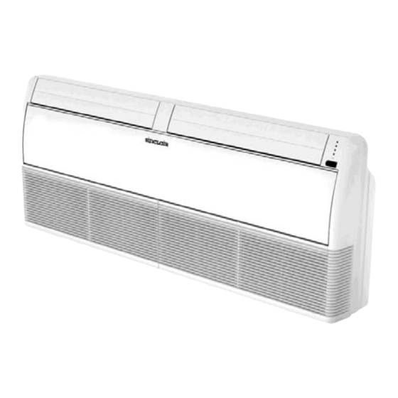
SERVICE MANUAL
FLOOR & CEILING
SERIES
ASF-12A, ASF-18A, ASF-24A, ASF-30A
ASF-36, ASF-48A, AS-60A
Table of
Contents
Previous
Page
Next
Page
1
2
3
4
5
Advertisement
Chapters
Table of Contents
3
Ceiling & Floor Type
8
Outdoor Units
39
Table of Contents
Need help?
Do you have a question about the ASF-12A and is the answer not in the manual?
Ask a question
Questions and answers
Related Manuals for Sinclair ASF-12A
Air Conditioner Sinclair ASF-12A User Manual
Floor & ceiling series (18 pages)
Air Conditioner Sinclair ASGE-09AIN WK Service Manual
New uni dc inverter series outdoor units asge-xxain wk indoor units-floor-ceiling, cassette, duct type (127 pages)
Air Conditioner Sinclair ASGE-18AI Service Manual
Dc inverter series (264 pages)
Air Conditioner Sinclair ASF-36 Service Manual
(80 pages)
Air Conditioner Sinclair ASGE-09A Service Manual
Uni on/off serie outdoor units: asge-**a indoor units: ascu-**a, asdu-**a, asfu-**a (202 pages)
Air Conditioner Sinclair ASFU-09A User Manual
Uni on/off series floor & ceiling units (50 pages)
Air Conditioner Sinclair ASF-60AN Service Manual
On/off series (96 pages)
Air Conditioner Sinclair ASF-60A User Manual
Floor & ceiling series (18 pages)
Air Conditioner Sinclair Uni Split Duct series User Manual
(28 pages)
Air Conditioner Sinclair ASF-60BI User Manual
Uni split floor-ceiling series (36 pages)
Air Conditioner Sinclair ASGE-48BI-3 User Manual
(36 pages)
Air Conditioner Sinclair ASC-BI Series Service Manual
(226 pages)
Air Conditioner Sinclair ASF BI Series User Manual
Uni split floor-ceiling series (36 pages)
Air Conditioner Sinclair ASF-12BI Service Manual
(226 pages)
Air Conditioner Sinclair UNI SPLIT ASF-12BI2 Service Manual
(224 pages)
Air Conditioner Sinclair ASF-18AIA User Manual
(64 pages)
This manual is also suitable for:
Asf-18a
Asf-30a
Asf-24a
Asf-36
Asf-48a
As-60a
Table of Contents
Print
Rename the bookmark
Delete bookmark?
Delete from my manuals?
Login
Sign In
OR
Sign in with Facebook
Sign in with Google
Upload manual
Upload from disk
Upload from URL


Need help?
Do you have a question about the ASF-12A and is the answer not in the manual?
Questions and answers