Sign In
Upload
Download
Table of Contents
Contents
Add to my manuals
Delete from my manuals
Share
URL of this page:
HTML Link:
Bookmark this page
Add
Manual will be automatically added to "My Manuals"
Print this page
×
Bookmark added
×
Added to my manuals
Manuals
Brands
Sinclair Manuals
Air Conditioner
ASGE-18AI
Service manual
Sinclair ASGE-18AI Service Manual
Dc inverter series
Hide thumbs
1
2
3
4
5
6
7
8
9
10
11
12
13
14
15
16
17
18
19
20
21
22
23
24
25
26
27
28
29
30
31
32
33
34
35
36
37
38
39
40
41
42
43
44
45
46
47
48
49
50
51
52
53
54
55
56
57
58
59
60
61
62
63
64
65
66
67
68
69
70
71
72
73
74
75
76
77
78
79
80
Table Of Contents
81
82
83
84
85
86
87
88
89
90
91
92
93
94
95
96
97
98
99
100
101
102
103
104
105
106
107
108
109
110
111
112
113
114
115
116
117
118
119
120
121
122
123
124
125
126
127
128
129
130
131
132
133
134
135
136
137
138
139
140
141
142
143
144
145
146
147
148
149
150
151
152
153
154
155
156
157
158
159
160
161
162
163
164
165
166
167
168
169
170
171
172
173
174
175
176
177
178
179
180
181
182
183
184
185
186
187
188
189
190
191
192
193
194
195
196
197
198
199
200
201
202
203
204
205
206
207
208
209
210
211
212
213
214
215
216
217
218
219
220
221
222
223
224
225
226
227
228
229
230
231
232
233
234
235
236
237
238
239
240
241
242
243
244
245
246
247
248
249
250
251
252
253
254
255
256
257
258
259
260
261
262
263
264
page
of
264
Go
/
264
Contents
Table of Contents
Bookmarks
Table of Contents
Models List
Air Conditioner
Product Data
Piping Diagram
Main Logic
Wireless Remote Controller
Wired Remote Controller
Centralized Controller
Control Wiring Design
Indoor Unit Installation
Outdoor Unit Installation
Table of Contents
Refrigeration Piping Work
Figure
Model
Electric Wiring Work
Asge-18Ai
Asge-24Ai
Asge-36Ai Sasge-36Ai-3 S
Asge-42Ai-3 S
Asge-36Ai Asge-36Ai-3
Advertisement
Quick Links
1
Models List
2
Air Conditioner
3
Product Data
4
Outdoor Unit Installation
5
Table of Contents
6
Electric Wiring Work
7
Asge-42Ai-3 S
8
Asge-36Ai Sasge-36Ai-3 S
Download this manual
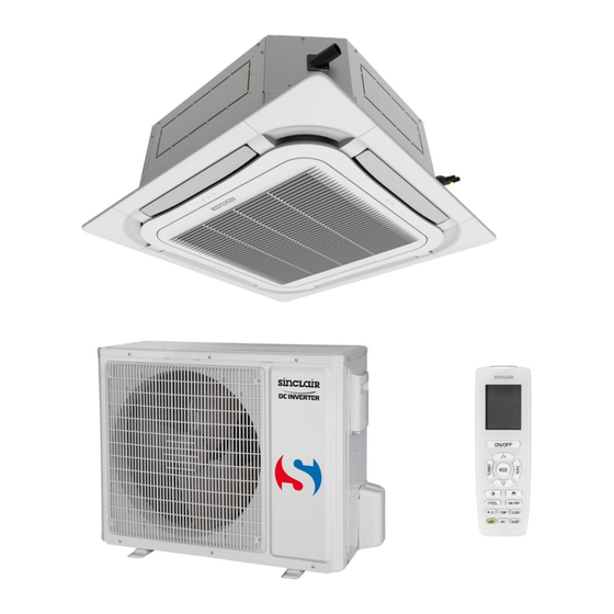
SERVICE MANUAL
DC INVERTER SERIES
OUTDOOR AND INDOOR UNITS
CASSETTE, FLOOR&CEILING, DUCT UNITS
OUTDOOR UNITS
Table of
Contents
Previous
Page
Next
Page
1
2
3
4
5
Advertisement
Table of Contents
Need help?
Do you have a question about the ASGE-18AI and is the answer not in the manual?
Ask a question
Questions and answers
Related Manuals for Sinclair ASGE-18AI
Air Conditioner Sinclair ASGE-18AIN WK Service Manual
New uni dc inverter series outdoor units asge-xxain wk indoor units-floor-ceiling, cassette, duct type (127 pages)
Air Conditioner Sinclair ASGE-24AIN WK Service Manual
New uni dc inverter series outdoor units asge-xxain wk indoor units-floor-ceiling, cassette, duct type (127 pages)
Air Conditioner Sinclair ASGE-24AI S Service Manual
Dc inverter series (264 pages)
Air Conditioner Sinclair ASGE-09A Service Manual
Uni on/off serie outdoor units: asge-**a indoor units: ascu-**a, asdu-**a, asfu-**a (202 pages)
Air Conditioner Sinclair ASGE-18A Service Manual
Uni on/off serie outdoor units: asge-**a indoor units: ascu-**a, asdu-**a, asfu-**a (202 pages)
Air Conditioner Sinclair ASGE-24A Service Manual
Uni on/off serie outdoor units: asge-**a indoor units: ascu-**a, asdu-**a, asfu-**a (202 pages)
Air Conditioner Sinclair ASC-BI Series Service Manual
(226 pages)
Air Conditioner Sinclair ASD-48BI User Manual
(35 pages)
Air Conditioner Sinclair ASC-18BI User Manual
Uni split cassette series (40 pages)
Air Conditioner Sinclair ASC-12BI User Manual
Uni split cassette series (40 pages)
Air Conditioner Sinclair ASC-36BI User Manual
Uni split cassette series (40 pages)
Air Conditioner Sinclair ASGE-36BI-3 User Manual
Uni split cassette series (40 pages)
Air Conditioner Sinclair ASGE-24BI Service Manual
(226 pages)
Air Conditioner Sinclair ASC-12BI2 Installation Manual
Uni split series cassette units (72 pages)
Air Conditioner Sinclair UNI SPLIT ASGE-48BI2 Service Manual
(224 pages)
Air Conditioner Sinclair UNI SPLIT ASGE-60BI2-3 Service Manual
(224 pages)
This manual is also suitable for:
Asge-24ai s
Asge-36ai s
Asge-36ai-3 s
Asge-42ai-3 s
Asd-18ai
Asd-24ai
...
Show all
Asd-36ai
Asd-42ai
Asf-18ai
Asf-24ai
Asf-36ai
Asf-42ai
Asc-24ai
Asc-18a
Asc-36ai
Asc-36ais
Asc-42ai
Table of Contents
Print
Rename the bookmark
Delete bookmark?
Delete from my manuals?
Login
Sign In
OR
Sign in with Facebook
Sign in with Google
Upload manual
Upload from disk
Upload from URL


Need help?
Do you have a question about the ASGE-18AI and is the answer not in the manual?
Questions and answers