Advertisement
Quick Links
Advertisement

Related Manuals for Make Noise Rene


Summary of Contents for Make Noise Rene
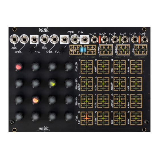
- Page 1 René v. 2.2...
- Page 2 (1) this device may not cause harmful interference, and (2) this device must accept any interference received, including interference that may cause undesired operation. Changes / modi cations not approved by the Make Noise Co. could void the user’s authority to operate the equipment.
-
Page 3: Limited Warranty
Limited WARRANTY: Make Noise warrants this product to be free of defects in materials or construction for a period of one year from the date of purchase (proof of purchase/invoice required). Malfunction resulting from wrong power supply voltages, backwards or reversed eurorack bus board cable connection, abuse of the product or any other causes determined by Make Noise to be the fault of the user are not covered by this warranty, and normal service rates will apply. -
Page 4: Electrocution Hazard
Eurorack style bus board, minding the polarity so that the RED stripe on the cable is oriented to the NEGATIVE 12 Volt line on both the module and the bus board. On the Make Noise 6U or 3U Busboard, the negative 12 Volt line is indicated by the white stripe. - Page 5 Overview: René is deep, but all you really need to know: Patch one clock to X CLK, and a second clock to Y CLK, adjust clock rates and/ or divisors, tune voltages per location (the knobs) as desired. Adjusting those two clocks relative to each other will create seemingly in nite variations on the theme that is your sequence.
- Page 6 René Panel Controls Inputs: X-CLK Input: Clock/Gate signal (of width greater than .5ms and amplitude greater than 2.5V) applied to this input drives the X-Axis Counter. If using MATHS to clock, then set Vari-Response to LINEAR. When René counts Snake Style, X-CLK steps linearly through a stored set of coordinates;...
- Page 7 René Panel Controls (cont’d) Sensivity: Touch Grid sensitivity control. To increase sensitivity, set the position 100% clockwise. Outputs: 10. QCV: The Quantized Control Voltage for the currently active location will appear at this output. QCV may also yield a Stored Quantized Voltage (if selected on Q Page), in which case the corresponding location potentiometer is no longer “live.”...
- Page 8 René Panel Controls (cont’d) Interface: 14. CV ProGraMming Grid: Potentiometers used for ProGraMing. Contain Location LED’s to indicate currently active Location(s). 17. PGM 1: [PRESS] to cycle through the ProGraM Pages 18. PGM 2: When in a ProGraM Page, [PRESS] to return to Play Mode. While in Play Mode, [PRESS] to latch currently-held Locations.
- Page 9 Controls 4x4 CV Programming grid: Potentiometers sets Tuned Voltage for corresponding Locations, 0 thru 15. 4x4 touch grid: In PLAY mode, the touch pads may be used to set ACCESS in real time, e ectively allowing the performer to play the ACCESS parameter. In use, this means that René will go to only the locations that the performer is touching.
- Page 10 ProGraM Pages These pages give the performer real time control over the deeper processes within René, allowing real time sculpting of the thought processes that drives the sequence. ACCESS: the performer Grants ACCESS or Denies ACCESS to any of the 16 Locations in the Touch Grid.
- Page 11 APPENDIX A (X FUN and Y FUN) Counting: FWD: for every Clock Pulse, associated counter advances one digit. 0, 1, 2, 3. After 3, counter returns to 0. BWD: for every Clock Pulse, associated counter recedes one digit. 3, 2, 1, 0. After 0, counter returns to PEND: for every Clock Pulse, associated counter advances from 0, 1, 2, 3 and then recedes 2, 1, 0.
-
Page 12: Logic Operations
Musically speaking, Seek moves more, and Sleep will rest more. Using Sleep and ProGraMming Access and Gates, it is possible to create rests, pauses and etc... LOGIC OPERATIONS There are 3 rows of the logic processing. CLK by MOD, Gate by MOD and Gate by Opposing CLK. With the Clock Logic Ops (locations 9, 10, 11) the MOD input is AND, OR, XOR against the CLocK and the result drives the counter for the associated Axis. - Page 13 APPENDIX B Stored Quantized Voltages While at the Quantize Page, to store all 16 Voltages as set by the potentiometers and the ProGraMmed Scale as set by touch grid Locations 0 thru 11, touch and hold either Location 12, 13, 14, or 15 until all 6 PGM LEDs ash.
- Page 14 APPENDIX C Snake: Memorized Coordinate Sets: These drawings illustrate the SNAKE like paths that René travels, reading coordinates from memory. Conceived and Illustrated by yerpa58.
- Page 15 X-Axis location whenever either clock goes “high. ” It is important to note, if one clock begins while the other clock is already HIGH, the Rene will NOT advance, as there is no state change:...
- Page 16 A clock patched to either the X-CLK or X-MOD input will advance the Rene to the next X-Axis Location; however, if both are high at the same time, the Rene does not advance. With this XOR activated, try running a low-frequency square wave into the X-CLK input for steady clock advancement while periodically sending a wide Gate signal to the X-MOD input in order to "invert"...
- Page 17 Voltage Controlled Raga: www.youtube.com/watch?v=DHf4q7pehtg (Adjust to Taste) Adjust Rene’s XCV input attenuator slowly up from 0% in order to gradually destabilize the sequence. Variation: 1. Turn Fold CCW and patch one of Rene’s Gate Outputs to the DPO’s STRIKE Input.
- Page 18 Quantization Level(s) Turn Stages On/O to control scale Variation: Patch MATHS EOC Output to Rene Y-CLK Input in order to switch snake patterns aftern each MATHS Function/Envelope cycle. Concept: “Arpeggiation” of a 4-step Sequence (No Sound as Depicted) Level of...
- Page 19 Process CV To Taste This feedback patch will cause Rene to jump locations every time it sends a CV value much greater than zero. Many nonlinear patterns await discovery. A “cluster” of higher CV values will cause extended sudden movement. “Eddies” can be created by setting several adjacent knobs to low values.
Need help?
Do you have a question about the Rene and is the answer not in the manual?
Questions and answers