Table of Contents
Advertisement
Quick Links
Advertisement
Table of Contents

Related Manuals for Make Noise MATHS


Summary of Contents for Make Noise MATHS
- Page 1 v2.5...
-
Page 2: Table Of Contents
MATHS Limited Warranty: ----------------------------------------------------2 Installation: ----------------------------------------------------------3 Overview: ---------------------------------------------------------4 CHannel 1 Panel Controls:-----------------------------------------5 CHannel 4 Panel Controls:--------------------------------------------7 SUM and OR Bus:-----------------------------------------------------9 Getting Started: -------------------------------------------------------11 Rise, Fall, and Vari-Response:-------------------------------------12 Signal Outputs:------------------------------------------------------13 Tips & Tricks: ---------------------------------------------------------14 Patch Examples:------------------------------------------------------15... -
Page 3: Limited Warranty
Limited WARRANTY: Make Noise warrants this product to be free of defects in materials or construction for a period of one year from the date of purchase (proof of purchase/invoice required). Malfunction resulting from wrong power supply voltages, backwards or reversed eurorack bus board cable connection, abuse of the product or any other causes determined by Make Noise to be the fault of the user are not covered by this warranty, and normal service rates will apply. -
Page 4: Installation
Eurorack style bus board, minding the polarity so that the RED stripe on the cable is oriented to the NEGATIVE 12 Volt line on both the module and the bus board. On the Make Noise 6U or 3U Busboard, the negative 12 Volt line is indicated by the white stripe. -
Page 5: Overview
Even small voltages will be readable on these LEDs. 3. As Make Noise now o ers a Multiple the Signal OUT Multiple (from the original MATHS) has been changed to a Unity Signal OUTput. Useful as it allows for creating two variations of output, one at unity and the other as processed through the Attenuvertor. -
Page 6: Channel 1 Panel Controls
14 15 MATHS Channel 1 1. Signal IN: Direct Coupled input to circuit. Use for Lag, Portamento, ASR (Attack Sustain Release type envelopes). Also input to SUM/ OR Bus. Range +/-10V 2. Trigger IN: Gate or Pulse applied to this input will trigger the circuit regardless of activity at the Signal IN. The result being a 0V to 10V function, aka Envelope, whose characteristics are defined by the Rise, Fall, and Vari-Response parameters. - Page 7 9. FALL CV IN: Linear control signal input for Fall parameter. Positive control signals increase Fall time, Negative control signals decrease Fall Time with respect to the Fall panel control. Range +/-8V 10. CYCLE IN: On Gate HIGH, circuit will CYCLE. On Gate LOW MATHS will not CYCLE (unless the CYCLE button is engaged). Requires minimum +2.5V for HIGH.
-
Page 8: Channel 4 Panel Controls
MATHS Channel 4 1. Signal IN: Direct Coupled input to circuit. Use for Lag, Portamento, ASR (Attack Sustain Release type envelopes). Also input to SUM/ OR Bus. Range +/-10V 2. Trigger IN: Gate or Pulse applied to this input will trigger the circuit regardless of activity at the Signal IN. The result being a 0V to 10V function, aka Envelope, whose characteristics are de ned by the Rise, Fall, and Vari-Response parameters. - Page 9 9. FALL CV IN: Linear control signal input for Fall parameter. Positive control signals increase Fall time, Negative control signals decrease Fall Time with respect to the Fall panel control. Range +/-8V 10. CYCLE IN: On Gate HIGH, circuit will CYCLE. On Gate LOW MATHS will not CYCLE (unless the CYCLE button is engaged). Requires minimum +2.5V for HIGH 11.
-
Page 10: Sum And Or Bus
SUM and OR Bus 1. Direct Coupled Channel 2 Signal INput to Attenuvertor and SUM/OR Bus. Normalized to a +10V reference for generation of voltage o sets. Input Range +/-10Vpp. 2. Direct Coupled Channel 3 Signal INput to Attenuvertor and SUM/OR Bus. Normalized to a +5V reference for generation of voltage o sets. - Page 11 SUM and OR Bus (cont’d) 7. CH. 1 Variable OUT: The applied signal as processed by CH. 1 controls. Normalized to the SUM and OR busses. Inserting a patch cable will remove the signal from the SUM and OR busses. Output Range +/-10V 8.
-
Page 12: Getting Started
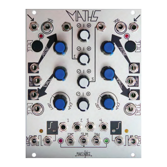
Getting Started MATHS is laid out top to bottom, with symmetrical features between CH. 1 and 4. The signal inputs are at the top, followed by the panel controls and control signal inputs at the middle. The signal outputs are at the bottom of the module. LEDs are placed near the signal they are indicating. -
Page 13: Rise, Fall, And Vari-Response
FALL controls determine how fast or slow the circuit will respond to signals applied to the Signal IN and Trigger IN. The range of times is larger than the typical Envelope or LFO. MATHS will create functions as slow as 25 minutes (Rise and Fall full CW and external control signals added to go into "slow-ver-drive") and as fast as 1khz (audio rate). -
Page 14: Signal Outputs
Signal OUTputs There are many di erent signal outputs on the MATHS. All of them are situated at the bottom of the module. Many of them have LEDs situated nearby for visual indication of the signals. The Variable OUTs These outputs are labelled 1, 2, 3 and 4 and are associated with the four Attenuvertor controls in the center of the module. These outputs are all determined by the settings of their associated controls, esp. -
Page 15: Tips & Tricks
-Use the INV SUM OUT where you require reversed modulation but do not have means for inversion at the CV destination (MIX CV IN on ECHOPHON for example). -Feeding an inverted signal from MATHS back into the MATHS at any of the CV inputs is highly useful for creating responses that are not covered by the Vari-Response control alone. -
Page 16: Patch Examples
Begin with Arcade Trill patch. set CH. 1 Attenuvertor to 1 o'clock. Apply CH. 1 Signal OUT to MMG DC Signal IN. Patch EOR to MMG AC Signal IN, set to LP mode, no feedback, starting with FREQ at full CCW. Apply MMG Signal OUT to MATHS CH. 4 Both IN. - Page 17 Patch Ideas: Analog Voltages, Triggered Functions/Envelopes Voltage Controlled Transient Function Generator (Attack/ Decay EG) A pulse or gate applied to the Trigger IN of CH. 1 or 4 will start the transient function which rises from 0V to 10V at a rate determined by the RISE parameter and then falls from 10V to 0V at a rate determined by the FALL parameter.
- Page 18 Patch Ideas: Analog Signal Processing, Voltage MATHS! ADD, Subtract Control Signals Apply signals to be added/ subtracted to any combination of Signal IN CH. 1,2,3,4 (when using CH. 1,4 RISE and FALL must be set to full CCW, and Cycle switch not engaged). For channels to be added, set Attenuvertor controls to full CW. Set Attenuvertors for channels to be subtracted to full CCW.
- Page 19 Patch Ideas: Analog Signal Processing, Voltage MATHS! Pseudo-VCA with clipping - Thanx to Walker Farrell Patch audio signal to CH. 1, with RISE and FALL at full CCW, or cycle CH. 1 at audio rate. Take output from SUM out. Set initial level with CH.
Need help?
Do you have a question about the MATHS and is the answer not in the manual?
Questions and answers