Table of Contents
Advertisement
Quick Links
Advertisement
Table of Contents

Related Manuals for Marantz VP-12S1s


Summary of Contents for Marantz VP-12S1s
- Page 1 Model VP-12S1 User Guide Projector...
-
Page 2: For The Customers In Canada
CAUTION: TO REDUCE THE RISK OF ELECTRIC SHOCK, REFER SERVICING TO QUALIFIED SERVICE PERSONNEL WARNING TO REDUCE THE RISK OF FIRE OR ELECTRIC SHOCK, DO NOT EXPOSE THIS APPLIANCE TO RAIN OR MOISTURE. CAUTION: TO PREVENT ELECTRIC SHOCK, MATCH WIDE BLADE OF PLUG TO WIDE SLOT, FULLY INSERT. -
Page 3: Important Safety Instructions
Kit approved by MARANTZ must be used for installation. Do not look into the lens when the projector is turned on. It could damage your eyesight. Unplug the projector from the wall outlet if it is not to be used for a few days. -
Page 4: Table Of Contents
Remote Controller ... 6 Preparing the Remote Controller ... 7 Recommended Setting ... 8 Distance between the projector and the screen (throw distance) ... 9 Image Position Adjustment ... 10 Advanced Setting ... 11 The Screen Image in a Wide screen (16:9) ... 12 The Screen Image in a 4:3 screen ... -
Page 5: Features
It is almost impossible to have zero pixel defects, even using the most advanced technology. This is not a problem only for Marantz, but all projector manufactures. Therefore we have to note that the warranty does not cover the DMD defects. -
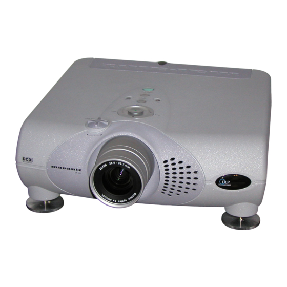
Page 6: Projector Layout And Functional Overview
Lens Shift knob Manually adjust the position of the image vertically. i POWER key Press to turn the projector ON or STANDBY mode. !1 o o POWER ON indicator Lights up when the power is turned on. Flashes while the projector goes into standby mode for about one minute. -
Page 7: Right Side And Rear
. REMOTE switch (EXTERNAL/INTERNAL) When using this projector independently, set this switch to "INTERNAL". When using this projector in a system with a Marantz DVD player or AV Receiver equipped with a remote sensor, set the switch to "EXTERNAL". ⁄0 TRIG.1(TRIGGER 1) When the unit is turned on, 12V is output. - Page 8 ⁄1 TRIG.2(TRIGGER 2) Select ON or OFF at each aspect mode, such as Full, Normal, Zoom, and Through to control screen aspect ratio with powered up/down dual aspect ratio screen. Note: Do not use TRIG.1 and TRIG.2, as the power source. ⁄2 LIGHT ON/OFF Select ON : The connector panel lights up.
-
Page 9: Bottom
Bottom q Adjustment lever Lift the projector and turn the adjustment lever right or left. The adjustable feet will extend from the projector. Then, release the lever, the adjustable feet is locked. Height Adjustment How to use adjustable feet and adjustment lever. -
Page 10: Remote Controller
When the key is pressed, the mode toggles Dynamic1, Dynamic2, Dynamic3 and Dynamic Default. Note : If you need discrete command for above picture modes, you can down load from "www.marantz.com". ¡3 INFO key ¡2 Turn the information menu on or off. -
Page 11: Preparing The Remote Controller
If the unit gets moistured, wipe it off immediately. – The Remote Controller operation may not function if the projector’s IR sensors are exposed to direct sun light or strong artificial light, or if there is an obstacle between the IR sensors and the Remote Controller. -
Page 12: Installation
V P - 1 2 S 1 Throw distance Note : Lens shift position is at Full up. CAUTION – For ceiling installation, consult with Marantz authorized dealer. – Do not look into the lens when the projector is turned on. It could damage your eyesight. -
Page 13: Distance Between The Projector And The Screen (Throw Distance)
Distance between the projector and the screen (throw distance) Screen size (Diagonal) V P - 1 2 S 1 16:9 screen Screen Size Throw distance (Diagonal) Minimum inch 40 inch 1,281 mm inch 60 inch 1,945 mm inch 80 inch... -
Page 14: Image Position Adjustment
Image Position Adjustment You can adjust the image position with the Lens Shift knob. Turn the Lens Shift knob to clockwise : The image goes up. • Maximum range to throw up : Bottom of the image correspond to the center of the Projection Lens. -
Page 15: Advanced Setting
Advanced Setting When the projecting image is a trapezoid, correct it in Keystone-V and/or Keystone-H in the Display Menu. Keystone-V(Electronic vertical keystone correction) Keystone-H(Electronic horizontal keystone correction) Note : Electronic horizontal keystone correction works properly when the lens shift position is at Full Up. SET UP PROCEDURES... -
Page 16: The Screen Image In A Wide Screen (16:9)
The Screen Images in a Wide screen (16:9) • Press the ZOOM key, the NORMAL key or the FULL key on the remote controller for the 4:3 aspect ratio video source. • Press the FULL key on the remote controller for 16:9 aspect ratio video source, such as 1080i, 1035i, and 720p video systems. •... -
Page 17: The Screen Image In A 4:3 Screen
• Press the ZOOM key, the NORMAL key or the FULL key on the remote controller for the 4:3 aspect ratio video source. • Press the FULL key on the remote controller for 16:9 aspect ratio video source, such as 1080i, 1035i, and 720p video systems. •... -
Page 18: Connection
CONNECTION When making connections be sure to: • Turn off all equipment before making any connections. • Use the proper cables for each connection. • Insert the plug properly. Any plugs that are not fully inserted often generate a noise. When pulling out a cable: •... -
Page 19: Connection With A Dv Camcoder
Connection with a DV camcoder Note: DV IN connector is available for DV-SD format of i.LINK(IEEE1394). Advanced connection RS-232C External Controller Control Adapter cable DV-SD OUT DIGITAL AUDIO IN Receiver equipment with a Dolby Digital decoder Screen 35mm Mini Plug (Mono) Ferrite core REMOTE CONTROL IN REMOTE CONTROL OUT... -
Page 20: Initial Set Up
Turn the Zoom ring to adjust the size of the image. Switch on the equipment connected to the projector. Press the INPUT SELECT key on the projector or the COMPONENT key, S-VIDEO key, VIDEO key, or RGB key on the remote controller. -
Page 21: Operations
OPERATIONS Menu Refer to the on-screen menu for making various adjustments and settings. Press the MENU key. The MENU appears. 3 / 4 / 1 / 2 keys to select a menu item. Make adjustments in Picture Adjust, Setting, Display, Configuration, Trigger2, or Memory. -
Page 22: Display
Display The following adjustments can be made: ITEM Keystone-V (Electronic vertical keystone correction) Keystone-H (Electronic horizontal keystone correction) Auto Adjust Picture Shift V Down Size V Small Picture Shift H Left Size H Small Phase Backward – Keystone H, V Adjust the trapezoid image to a rectangle image. -
Page 23: Trigger2
– Reset Lamp Life When replace the lamp unit, before the Lamp Life becomes "0" hours need to reset lamp life. When the user selects “Yes”, the following message appears: Again, select “Yes”, and press the ENTER key. Then the lamp life is initialized. -
Page 24: Lamp Life And Replacement Lamp
Lamp Life becomes less than 100 hours . • The projector is designed not to turn on after the lamp use has exceeded 2000 hours. (Lamp Life 0 HOUR) If the projector is in use, it will turn off. -
Page 25: Maintenance
• Do not loosen any screws except for those mentioned below. • The lamp may break if handled improperly. • Do not use other than a Marantz replacement lamp unit. How to replace the Lamp Unit WARNING: • The lamp itself may get hot. Be careful when handling. -
Page 26: Troubleshooting
The “EXTERNAL” position on the connector panel is selected. Notes: • If the lamp still does not function after the replacement and initialization of the lamp life, contact Marantz authorized dealer, or service center. ERROR MODE WARNING/LAMP indicator, POWER ON indicator, and STANDBY indicator diagnose error mode of the projector as follows. -
Page 27: On Screen Message
Use the list below to check the message displayed on the screen. Message NO SIGNAL No input signal. REPLACE LAMP! The lamp has reached the end of its life. Improper signal feed to the projector. OUT OF RANGE SPECIFICATIONS 7 Optical characteristics Panel 0.85inch 16:9... - Page 28 7 Timing chart System NTSC PAL-B/G SECAM 480/60p 576/50p 1035/60i 1080/60i 1080/50i 1080/48i 720/60p 720/50p 720/48p 540/60p 640x350 640x350 640x400 640x400 640x480 640x480 640x480 640x480 800x600 800x600 800x600 800x600 800x600 1024x768 1024x768 1024x768 1024x768 1024x768 Note: The systems marked #1 are not displayed properly. V ( Hz ) Resolution 768x240...
-
Page 29: Dimensions
DIMENSIONS 7 TOP 7 FRONT 5/8 - 2 (15 - 61.8 mm) 7 BOTTOM inch inch 3/16 (182.5 mm) (222 mm) inch 15/16 (404.5 mm) inch [Adjustable] 7/16 inch inch 11/16 5/16 (93.5 mm) (110 mm) 3/4 inch (19.8 mm) inch inch 3/16... - Page 30 P.O. Box 685, Bell Village, Port Louis, Mauritius PO BOX 1280, Sandhausen 69200, Germany A division of Marantz Europe B.V., Building SFF2, P.O. Box 80002, 5600 JB Eindhoven, The Netherlands 14 Malvern Road, Mt. Albert, Auckland, New Zealand Sandkerveien 64, Oslo 0483, Norway P.O.
Need help?
Do you have a question about the VP-12S1s and is the answer not in the manual?
Questions and answers