Table of Contents

Related Manuals for Manley Langevin Dual Vocal Combo


Summary of Contents for Manley Langevin Dual Vocal Combo
- Page 1 OWNER'S MANUAL LANGEVIN DUAL VOCAL COMBO MANLEY LABORATORIES, INC. MANUFACTURED BY: MANLEY LABORATORIES, INC. 13880 MAGNOLIA AVE. CHINO, CA. 91710 USA TEL: (909) 627-4256 FAX: (909) 628-2482 email:emanley@manleylabs.com http://www.manleylabs.com...
-
Page 2: Table Of Contents
SECTION INTRODUCTION FRONT PANEL BACK PANEL MIC PRE BASICS CONNECTING YOUR PREAMPLIFIER OPERATION NOTES SPECIFICATIONS TROUBLESHOOTING INTERNAL ADJUSTMENTS REPLACING FUSES AND METER LAMPS MAINS CONNECTIONS WARRANTY WARRANTY REGISTRATION APPENDIX A: WIRING YOUR OWN CABLES APPENDIX B: TEMPLATE FOR STORING SETTINGS CONTENTS PAGE 4, 5... -
Page 3: Water & Moisture
THANK YOU!... for choosing the Langevin Dual Vocal Combo. Manley Labs bought all the rights to the Langevin name and circuits in 1992. Manley uses the Langevin name for its solid state products including versions of an all discrete Pultec and Electro-Optical Limiter, and Mic Preamp. -
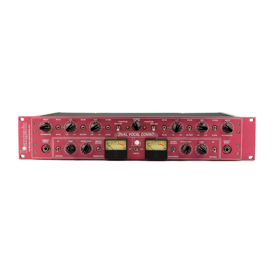
Page 4: Front Panel
INPUT INPUT 80 Hz L.F. L.F. EQ IN EQ IN ATTENUATE ATTENUATE 40 Hz EQ OUT EQ OUT DIRECT DIRECT GAIN GAIN REDUCTION REDUCTION INPUT INPUT BYPASS BYPASS The Dual Vocal Combo has 2 channels which are mirror images of each other and is further divided into top and bottom sections which correspond to the Mic Pre with EQ and the Opto-Limiter Sections. - Page 5 J) DIRECT INPUT. This is for plugging in an electric guitar, bass, synth, etc into the Dual Vocal Combo. The input impedance is high (150 kOhms) appropriate for these instruments and there should be plenty of gain available. Electric guitars and basses may need a fair amount of H.F. Boost to sound comparable to an amp because there happens to be a lot of H.F.
-
Page 6: Back Panel
BALANCED BALANCED MIC IN LINE OUT LINE OUT UNBALANCED UNBALANCED LIMITER LIMITER IN IN CHANNEL 2 CHANNEL 2 A) LIMITER IN. This is a balanced input that allows you to get a signal straight into the opto-limiter without going through the mic pre and EQ. As soon as you insert a plug into this jack, it breaks the normal signal path from the EQ. -
Page 7: Mic Pre Basics
This Microphone Preamp, like most mic preamps, is pretty easy to use. First we can discuss why outboard mic pre's have become "a must have item" in almost every studio even though your console probably has a bunch of them and that manufacturer claims that they are really great and you don't need outboard mic pre's. -
Page 8: Connecting Your Preamplifier
CONNECTING YOUR PREAMPLIFIER Easy - Connect the mic to the Microphone Input XLR, then connect the Line Output to your tape machine or console. Read on, there are some things to consider. On the back panel are female XLR's labelled MIC INPUT A and MIC INPUT B. The signal from the MICROPHONES get plugged in here. - Page 9 General advise - try it each way - listen, with vocals, always ask the singer which way they prefer. The headphones may "cancel" with the sound they hear in their skull while singing. This Mic Pre has no provision for changing the polarity. If you are recording direct to tape it is a good idea to have a few phase reverse adapters on hand.
-
Page 10: Operation Notes
The Langevin Electo-Optical Limiter follows certain traits and traditions established by the UREI LA-3A and similar levelling amplifiers. These traits can be divided into two aspects - electronic and operation. The electronic concept is simple and rather clean. Use the audio to light up LEDs which shine onto photo-resistors. - Page 11 The slope or ratio is also difficult to simulate. The initial ratio is low and becomes higher with more gain reduction until the leds light up fully and further reduction is not easy. This upper limit of reduction is in the area of 20 dB or at the bottom of the GR meter where the ratio becomes low again but this would be a severe setting that few engineers could use.
-
Page 12: Specifications
SPECIFICATIONS Frequency Response THD & Noise Signal to Noise ratio Headroom Maximum Output Maximum Input (with Input at max) Maximum Gain (factory set for 45 dB) Maximum Limitting Attack Time (fixed) Release Time (fixed) Input Impedance (optimised for mics with 100 to 600 ohm output impedances) Output Impedance XLR Pin-Out (balanced) (not appropriate for driving unbalanced inputs)PIN 2 = HOT (+) -
Page 13: Troubleshooting
TROUBLE-SHOOTING There are a number of possible symptoms of something not quite right, some may be interfacing, others we will touch on as well. The Dual Vocal Combo has a variety of balanced and unbalanced inputs and outputs optimised for typical standards and most problems are due to the right cable in the wrong jack. - Page 14 HUM - Let's assume it knows the words. Once again - several possibilities - several cures. Most likely it is a ground loop. The two most common procedures are: try a 3 pin to 2 pin AC adapter (about a dollar at the hardware store) which is better than messing up the power cable by bending the ground pin until it breaks off.
-
Page 15: Internal Adjustments
INTERNAL ADJUSTMENTS +36 Volt DC adjust with meter from ground to resistor marked by arrow. Check this first and adjust if needed. It is the power supply regulator adjustment. Now for the audio ... You will have to start out by setting front panel controls to these settings. BYPASS mode, SEP ( LINK OFF ), REDUCTION controls counter clockwise (MIN), GAIN to 1:00 or unity, Balance at 12:00. -
Page 16: Replacing Fuses And Meter Lamps
Changing the meter lamps is pretty easy. These are simple incandescent bulbs chosen for long life but eventually they will fail. They are always available from Manley Labs but most electronic stores will also have them (Radio Shack part number 272-1143) and are described as "Midget Screw-Base Lamps", 12 Volts @ 75 1) Disconnect the IEC AC mains for safety 2) Remove the two small Phillips head screws located at the back which hold the perforated top cover in place. -
Page 17: Mains Connections
MAINS CONNECTIONS Your unit has been factory set to the correct mains voltage for your country. The voltage setting is marked on the serial badge, located on the rear panel. Check that this complies with your local supply. The voltage changeover switch is located inside the unit in the middle of the PCB near the power transformer. -
Page 18: Warranty
WARRANTY... -
Page 19: Warranty Registration
WARRANTY REGISTRATION We ask that you please fill out this registration form and mail the bottom half to: MANLEY LABORATORIES REGISTRATION DEPARTMENT 13880 MAGNOLIA AVE. CHINO CA, 91710 or FAX to: (909) 628-2482 or email service@manleylabs.com with the info from below and a note that this is for warranty registration. -
Page 20: Appendix A: Wiring Your Own Cables
TEMPLATE -photocopy this page and use it to store settings INPUT INPUT 80 Hz L.F. L.F. EQ IN EQ IN ATTENUATE ATTENUATE 40 Hz EQ OUT EQ OUT DIRECT DIRECT GAIN GAIN REDUCTION REDUCTION INPUT INPUT BYPASS BYPASS PRODUCER: STUDIO: ARTIST: TRACK: NOTES:...
Need help?
Do you have a question about the Langevin Dual Vocal Combo and is the answer not in the manual?
Questions and answers