
Related Manuals for Manley CORE


Summary of Contents for Manley CORE
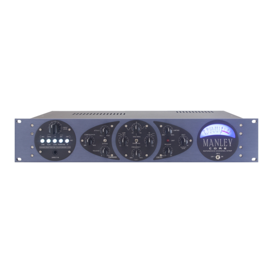
- Page 1 MANLEY CORE ® REFERENCE CHANNEL STRIP Designed & Handcrafted in the USA Manley Laboratories, Inc. 13880 Magnolia Avenue Chino, CA 91710 USA www.manley.com OWNER’S MANUAL...
-
Page 2: Table Of Contents
Reference ® Channel Strip. Manley Laboratories, Inc. reserves the right to make changes in specifications and other information contained in this publication without prior notice. Manley Laboratories, Inc. shall not be liable for errors contained herein or direct, indirect, incidental or consequential damages in connection with the furnishing, performance, or use of this material. -
Page 3: Introduction
3. Heat & Ventilation – When installing The CORE in a rack or any other location, be sure there is adequate ventilation. Improper ventilation will cause overheating, and can damage the unit. The unit should be situated away from heat sources, or other equipment that produce heat. -
Page 4: The Front Panel
DIRECT IN, Instrument input. This 1/4 inch input jack is for use with guitars, keyboards, or any other instrument. When a plug is inserted the CORE will automatically switch to the DI input. The Mic/Line switch must be set to the Line position to activate the DI. -
Page 5: Elop ® Compressor & Equalizer
ELOP COMPRESSOR ® The ELOP® Compressor utilizes our famous circuit topology as found in the VOXBOX®, and is also similar to the ELOP® and SLAM limiters. The COMPRESSION (Threshold) control determines at what level the compressor begins to act. Clockwise rotation makes the compressor reduce the signal. -
Page 6: Limiter & Vu Meter
– not a hard and fast rule – but if you are pinning it all the time (unless for an intentional effect) or the needle isn’t moving at all, you might need to adjust the input gain of the CORE. -
Page 7: The Rear Panel
THE REAR PANEL... -
Page 8: Operational Notes
If it’s necessary to connect to a unbalanced input, a cable must be used that has NO connection on XLR pin 3. This is important in order to prevent damage to the CORE, as well as distortion to the signal. -
Page 9: Questions
“loop”. Try and resolve any grounding issues in your setup by using dedicated cabling etc. If you cannot remove a ground loop in your setup, you can disconnect the Signal Ground from the Chassis ground on the Core by removing the Ground Lift jumpers, as shown in Diagram 9 (detailed instructions on page 11). -
Page 10: Servicing & Calibration
CALIBRATION / INTERNAL ADJUSTMENTS - FOR EXPERIENCED TECHNICIANS ONLY* *Experienced Technicians Only The CORE requires calibration for 3 sections of its circuitry: The calibration procedures 1) VU METER- Adjust: +4dBu (1.228 Volts RMS) = “0” VU, Meter “GR” zero set... - Page 11 2dB. The LED indicator should turn OFF. Note 1: if you do not have enough output level coming from your oscillator, then increase the signal level coming into the CORE by adjusting the INPUT LEVEL ATTENUATOR control. Bring up the input level attenuator until you have a reading of +21dBu at the output XLR “OP2”.
-
Page 12: Curves & Specifications
CURVES & SPECIFICATIONS • ALL-TUBE preamplifier audio path using 1 x 12AX7WA for gain and 1 x 6922 White Follower • Balanced Transformer Coupled XLR Microphone Input Impedance: 1250 Ohms • Balanced XLR Line Input Impedance: 10 kOhms • Unbalanced 1/4” Direct Input Impedance: 10 Meg Ohm •... - Page 14 No statement contained in this publication, including statements regarding suitability or performance of products shall be considered a warranty by Manley Laboratories, Inc. for any purpose or give rise to any liability of Manley Laboratories, Inc.
Need help?
Do you have a question about the CORE and is the answer not in the manual?
Questions and answers