Vulcan-Hart MG12 Installation & Operation Manual
Mg series gas restaurant
modular range
Hide thumbs
Also See for MG12:
- Installation & operation manual (16 pages) ,
- Specifications (2 pages) ,
- Service manual (20 pages)
Table of Contents
Advertisement
Quick Links
See also:
Service Manual
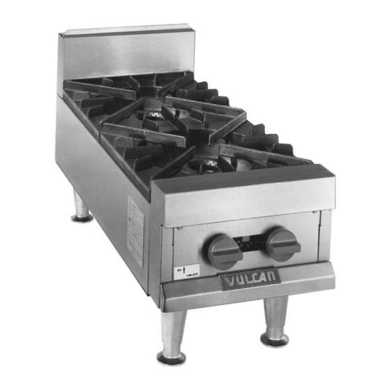
INSTALLATION & OPERATION MANUAL
FOR MG SERIES GAS RESTAURANT
MODULAR RANGE
For additional information on Vulcan or to locate an authorized parts and
service provider in your area, visit our website at www.vulcanequipment.com
©ITW Food Equipment Group, LLC
3600 North Point Blvd.
Baltimore, MA 21222
MODELS
MG12
MG24
MG36
MG48
MG60
RETAIN THIS MANUAL FOR FUTURE USE
ML-52549
ML-52514
ML-52522
ML-52523
ML-52524
FORM F-30832 (10-15)
Advertisement
Table of Contents

Subscribe to Our Youtube Channel
Related Manuals for Vulcan-Hart MG12


Summary of Contents for Vulcan-Hart MG12
- Page 1 INSTALLATION & OPERATION MANUAL FOR MG SERIES GAS RESTAURANT MODULAR RANGE MODELS MG12 ML-52549 MG24 ML-52514 MG36 ML-52522 MG48 ML-52523 MG60 ML-52524 For additional information on Vulcan or to locate an authorized parts and service provider in your area, visit our website at www.vulcanequipment.com RETAIN THIS MANUAL FOR FUTURE USE ©ITW Food Equipment Group, LLC...
-
Page 2: For Your Safety
IMPORTANT FOR YOUR SAFETY THIS MANUAL HAS BEEN PREPARED FOR PERSONNEL QUALIFIED TO INSTALL GAS EQUIPMENT, WHO SHOULD PERFORM THE INITIAL FIELD START-UP AND ADJUSTMENTS OF THE EQUIPMENT COVERED BY THIS MANUAL POST IN A PROMINENT LOCATION THE INSTRUCTIONS TO BE FOLLOWED IN THE EVENT THE SMELL OF GAS IS DETECTED. -
Page 3: Mg Series Gas Restaurant Modular Range Models
MG SERIES GAS RESTAURANT MODULAR RANGE MODELS __________________________________________________________________________________... -
Page 4: Table Of Contents
TABLE OF CONTENTS MG SERIES GAS RESTAURANT MODULAR RANGE MODELS…………………… 3 INSTALLATION…………………………………………………………………………….. 5 Uncrating…………………………………………………………………………..Location…………………………………………………………………………….. Installation Codes And Standards……………………..………………………… Assembly…………………………………………………………………………… Leveling……………………………………………………………………………... 11 Gas Connections…………………………………………………………………... 11 Testing The Gas Supply System………………………………………………… Flue Connections………………………………………………………………….. Lighting And Shutting Down The Pilots…………………………………………. OPERATION……………………………………………………………………………….. Controls……………………………………………………………………………... 14 Before First Use……………………………………………………………………. -
Page 5: Installation
If the supply and equipment requirements do not agree, do not proceed with the installation. Contact your dealer or Vulcan-Hart Company immediately. LOCATION The equipment area must be kept free and clear of combustible substances. -
Page 6: Installation Codes And Standards
The range must be installed so that the flow of combustion and ventilation air will not be obstructed. Adequate clearance for air openings into the combustion chamber must be provided. Make sure there is an adequate supply of air in the room to allow for combustion of the gas at the burners. - Page 7 CLEANING – GRIDDLE PLATE section of this manual. 3. Remove griddle plate. With one person at either side of the griddle, gently lift griddle straight up. DO NOT pull griddle forward until the third person has checked to ensure that the capillary bulb(s) (thermostatically controlled models only) are freed from the underside of the of the griddle plate.
- Page 8 b. Two 7" x 4" (17 cm x 10 cm) bricks, one to each side of the rear burner baffle area (see Fig. 1). 7. If the burner has been strapped down, use wire cutters to remove the wire strapping device. 8.
- Page 9 Check the backsplash component parts against the list below to ensure that all the required parts for the backsplash installation have been obtained. • If any parts are missing, contact your dealer or closest parts depot immediately. MODELS MG12 MG24 MG36 MG48...
- Page 10 It may be necessary to pull the heat shield bottom out slightly in order to clear the flue box. Be sure the backsplash is resting evenly and the channel holes are lining up with the holes provided in the right- and left-hand body side (see Fig’s. 3 & 4). Fig.
-
Page 11: Leveling
LEVELING Check the leveling of the range. Place a carpenter’s level across the range top plates. Level front to back and side to side. To adjust the leveling, tilt the range to one side and, using channel locks, unscrew the adjustable leg insert as required. -
Page 12: Testing The Gas Supply System
Prior to lighting, check all joints in the gas supply line for leaks. Use a soap and water solution. Do not use an open flame. After piping has been checked for leaks, all piping receiving gas should be fully purged to remove air. - Page 13 Nightly Shutdown Turn burner valve OFF; pilot will remain lit. Complete Shutdown Turn burner valve OFF; pilot will remain lit. Turn main gas supply OFF. Open Top Burners Turn main gas supply ON. Turn all top burner valve knobs ON to purge gas line of air. Turn top burner valve knobs OFF.
-
Page 14: Operation
OPERATION The range and its parts are hot. Be very careful when operating, cleaning or servicing the range. CONTROLS OPEN TOP BURNER KNOB — Regulates gas flow to top burners. To increase heat, turn knob counterclockwise; to decrease, turn knob clockwise. HOT TOP OR GRIDDLE TOP BURNER KNOB —... -
Page 15: Cleaning
CLEANING ® Do not use Dawn dish detergent to clean the exterior or interior components of the range. Do not use scouring powder; it is extremely difficult to remove completely and can build up accumulations that will damage the oven. Vulcan painted surfaces may be cleaned using a soft cloth and mild detergent solution. -
Page 16: Maintenance
Daily Thoroughly clean backsplash, sides and front. Remove grease drip tray and pan, empty and wash out in the same manner as any ordinary cooking utensil. Clean griddle surface thoroughly. If necessary, use a griddle stone, wire brush or steel wool over the surface.
Need help?
Do you have a question about the MG12 and is the answer not in the manual?
Questions and answers