Table of Contents
Advertisement
Quick Links
INSTALLER: Leave this manual with the appliance.
CONSUMER: Retain this manual for future reference.
These instructions are supplementary to the Installation and
Operating Instructions supplied with the fireplace and should be kept
together. Refer to the Installation and Operating Instructions for proper
gas supply, safety requirements and operating instructions
270315-16
TC30
HEARTWOOD
BURNER INSTALLATION
INSTRUCTIONS
PART# TC30.NG05D
FOR TC30 Series D
Fireplaces
TC30_NG05D
5056.42905D
Advertisement
Table of Contents

Related Manuals for Town & Country Fireplaces TC30.NG05D

Summary of Contents for Town & Country Fireplaces TC30.NG05D
- Page 1 Operating Instructions supplied with the fireplace and should be kept together. Refer to the Installation and Operating Instructions for proper gas supply, safety requirements and operating instructions TC30 HEARTWOOD BURNER INSTALLATION INSTRUCTIONS PART# TC30.NG05D FOR TC30 Series D Fireplaces 270315-16 TC30_NG05D 5056.42905D...
-
Page 2: Contents Of Package
Contents of Package • BURNER ASSEMBLY (including pilot and manifold) • LOG GRATE • TC30 HEARTWOOD LOGS • EMBER MATERIAL • HARDWARE PACKAGE • AIR DEFLECTOR • COAL CHUNKS • VERMICULITE Burner Installation 1. Place the keyhole slots in the burner Fig. # 1a over the two screws located in the firebox If this fireplace is to be base. (Fig. #1 & 1a) used on Propane please... - Page 3 Burner/ Grate Installation Fig. # 2 4. Secure the electrical bulkhead plate (Fig.#2) and gasket to the firebox. (2 screws) Attach the ignition and sensor wires to the module. (Fig.#3). 2 SCREWS BULKHEAD PLATE Fig. # 3 IGNITION FLAME INTERFACE WIRE SENSOR MODULE (RED) WIRE (WHITE) TC30_ng05D 270315-16...
- Page 4 5. A ttach the pilot and gas supply tubes to Fig. # 3b the bulk head fitting and tighten. (Fig. # 3b) Ensure the connections are gas tight. Conceal the spark and sensor wires below the supply tubes. A panel set must now be installed. See Installation and Operating Instructions manual for details. PILOT SUPPLY TUBE MAIN GAS SUPPLY...
-
Page 5: Ember Material Placement
Ember Material A large bag of ember material is shipped with the fireplace and needs to be installed on the burner to ensure optimum performance and flame appearance. A bag of coal chunks and lava rock is also supplied this must only be used around the burner pan to cover up the gas lines and brackets. 1. P ull apart the material into ember size pieces (approximately 1” square) and gently place them into the burner pan. Do not compress, leave them loose for best performance. -
Page 6: Log Placement
Log Placement Gas plumbing and vent connections Fig. # 7 should be completed before proceeding. The logs are fragile, and should be handled with care. Unpack and inspect log set. There should be a total of seven logs. BASE LOG, #1 Position the logs as indicated by the following pictures. The seven main logs have holes and / or pins. Engage each pin in the c orresponding holes. - Page 7 Fig. #9 LEFT FRONT LOG, #3 Fig. #10 LOG WITH HOLE, #4 TC30_ng05D 270315-16 5056.42905D...
- Page 8 Fig. #11 RIGHT CENTER LOG, #5 Fig. #12 FRONT RIGHT LOG, #6 TC30_ng05D 270315-16 5056.42905D...
-
Page 9: Center Twig
Fig. #13 RIGHT BASE LOG, #7 Fig. #14 CENTER TWIG, #8 Fig. #15 CENTER BASE CHUNK, #9 TC30_ng05D 270315-16 5056.42905D... -
Page 10: Propane Conversion
Propane Conversion If the unit is to be used on propane, convert as follows using the compo- nents supplied with this fireplace: Note: Factory supplied components must be used to ensure correct input. After conversion confirm proper manifold pressure. CAUTION The gas supply and electrical power must be shut off before proceeding with the conversion. - Page 11 Fig. # 19 7. W ith a 7/16” wrench loosen the pilot head on the pilot assembly by a half-turn (Fig. #19) 8. S lide the pilot adjustment band over and ensure that the hole in the orifice band is showing. (Fig. #20 shows NG position, Fig. # 21 shows LP position) Fig. # 20 Fig. #21 NG Position (Fig#20) LP Position (Fig #21) HOLE ADD DATE...
-
Page 12: Gas Pressure Check
Gas Pressure Check Note: To test the gas pressure, turn off the gas supply before removing the plug from the supply pressure test port or manifold pressure test port. Verify gas pressures with the fireplace lit and on the highest setting. SUPPLY MANIFOLD Remove the plug from the manifold test... -
Page 13: Flame Adjustment
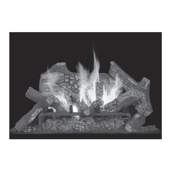
Flame Adjustment The air shutter on the burner tube controls the primary combustion air to the gas burner and is preset at the factory for natural gas fuel. Some adjustment may be necessary to obtain desired flame and to eliminate carbon deposits. Evaluate flame appearance after the fireplace has reached operating temperature. See Fig. #24 for proper flame pattern. Open primary air shutter if the logs, glass, and firebox have carbon accumulation and / or the flames are long, dark and stringy. The shutter may also be opened to enhance the Ember Material glow and lessen the flame height. -
Page 14: Replacement Parts
Replacement Parts (WHEN ORDERING, INCLUDE PART NUMBER WITH DESCRIPTION) ITEM ..DESCRIPTION .............PART NO. ITEM ..DESCRIPTION ........... PART NO. #4..PILOT ASSEMBLY......TCRP.5005025 #1..TC30.NG05 BURNER ASSEMBLY ..TC30.NG05D #5..MAIN SUPPLY TUBE (FLEX) .....5019.223 #2..HEARTWOOD LOG SET ......5094.302318 #3..ORIFICE, NATURAL GAS (#32)....5021.332A KIT CONTENTS: #1.. - Page 15 TC30_ng05D 270315-16 5056.42905D...
- Page 16 © 2015 Copyright Pacific Energy Fireplace Products LTD Reproduction, adaptation, or translation without prior written permission is prohibited, except as allowed under the copyright laws. For technical support, please contact your retailer. www.townandcountryfireplaces.net 2975 Allenby Rd., Duncan, BC V9L 6V8 Printed in Canada...
Need help?
Do you have a question about the TC30.NG05D and is the answer not in the manual?
Questions and answers