Table of Contents
Advertisement
Advertisement
Table of Contents

Related Manuals for Chauvin Arnoux C.A 5277


Summary of Contents for Chauvin Arnoux C.A 5277
- Page 1 C.A 5277 AC+DC TRMS MULTIMETER ENGLISH User’s manual...
- Page 2 E.g. Measurement on equipment installed upstream of the main fuse or building installation cut-off switch. You have just purchased a C.A 5277 multimeter and we thank you for your confidence in our products. To obtain the best service from your instrument: Read these instructions carefully;...
-
Page 3: Table Of Contents
CONTENTS 1. OVERVIEW .................................3 The display ............................4 1.2. The keys ..............................6 1.3. The switch..............................6 1.4. The terminals ............................7 2. Use ..................................7 First use ..............................7 Starting up the multimeter ........................7 Turning off the multimeter........................7 The stand...............................7 3. Functions................................8 Switch functions.............................8 Key functions ............................14 4. -
Page 4: Overview
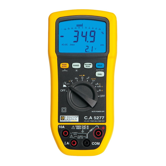
1. OVERVIEW The C.A 5277 is a stand-alone portable digital multimeter specially designed to combine all the functions for measurement of the following electrical quantities in a single instrument: AC Voltage measurement with low input impedance (voltage measurements for electrical and electrical engineering... - Page 5 1.1.1 The display symbols Symbols Description Measurement of the AC signal Measurement of the DC signal AC + DC Measurement of the AC and DC signal AUTO Auto-ranging Δ Relative values compared with a reference Δ Presence of a relative value in memory HOLD Memorisation and display of memorised values Maximum RMS value...
-
Page 6: The Keys
1.2. The keys Δ The keyboard has five keys: MODE AC/DC, RANGE, MAX/MIN/PEAK, REL and HOLD. These are the keys: Figure 2: the keyboard keys N°. Function Selection of the display mode. Selection of the measurement scale and activation/deactivation of the screen backlighting ( Activation of the MAX/MIN/PEAK mode Memorisation of the values and display mode Activation or deactivation of the automatic instrument shut-down... -
Page 7: The Terminals
1.4. The terminals These are the multimeter terminals: N°. Input 6 A, 10 A current 20 µA, 6000 µA, 60 mA, 600 mA current Other measurements Common Figure 4: the terminals The terminals can be used to carry out the measurements using test-probe leads or the temperature sensor shipped with the instrument. -
Page 8: Functions
3. FUNCTIONS 3.1 Switch functions To access the , or function, turn the switch to the selected function position. Every position (except OFF) is confirmed by a beep. 3.1.1 Types of measurements Below are the possible combinations depending on the type of measurement: Measurement type Max / Min Peak+... - Page 9 To measure a voltage, proceed as follows: 1. Set the switch to 2. Select the type of signal (AC, DC or AC+DC) by pressing Depending on your selection, the screen will display AC, DC or AC+DC 3. Connect the black lead to the COM terminal and the red lead to "+"; 4.
- Page 10 3.1.4 Resistance measurement To measure the resistance, proceed as follows: 1. Set the switch to 2. Connect the black lead to the COM terminal and the red lead to "+"; 3. Place the test probes on the terminals of the component; Remark: all resistance measurements must be performed with the power off.
- Page 11 3.1.6 Diode test To measure and check a semiconductor junction, proceed as follows: 1. Set the switch to 2. Press twice on . The symbol is displayed; 3. Connect the black lead to the COM terminal and the red lead to "+"; 4.
- Page 12 3.1.8 Temperature measurement To measure the temperature, proceed as follows: 1. Set the switch to 2. Press to select the unit and scale of the temperature (° C or ° F). Remark: the default measurement unit displayed is ° C 3.
- Page 13 Measurement in 1. Set the switch to 2. Select the type of signal (AC, DC or AC+DC) by pressing . Depending on your selection, the screen will display AC, DC or AC+DC 3. Connect the black lead to the COM terminal and the red lead to "10A"; 4.
-
Page 14: Key Functions
3.2 Key functions The functions: can be accessed by pressing a key repeatedly, using short or long presses. The long-press function is shown by the pictogram under the key. The functions are not exclusive, they can be combined. It is therefore possible to have min/max peak relative or just relative. In the same way, the Hold mode does not stop the min/max peak surveillance, it only freezes the display. - Page 15 • mode Type of press Resulting action Displays the bar-graph with graduation from zero to full scale or central short or long zero ( Selects the display mode for the quantity measured, i.e.: - the relative measurement in the unit for the quantity measured: Measured quantity –...
- Page 16 3.2.2 This key is used to manually select a measurement range or to activate the screen backlighting. The range defines the maximum range for measurements performed with the instrument. Remark: the Auto Range mode is activated by default. • In normal mode Type of press Resulting action short...
- Page 17 mode • Type of press Resulting action short exit from mode.
- Page 18 3.2.3 This key displays the MAX, MIN, PEAK+ or PEAK- modes. Max and Min fill in the highest and lowest values of the measurement. Peak+ displays the instant maximum peak value and Peak- displays the instant minimum peak value for the measurement.
- Page 19 3.2.4 This key is used to memorise the measurements and quantities or to deactivate the automatic power-off function on the instrument. • In normal mode Type of press Resulting action memorises a measurement status at a given moment and then short makes it possible to view them successively on the display.
- Page 20 • mode Type of press Resulting action freezes the measured quantity and reference value; short Δ Example: display screen V HOLD MEM. quits the mode. activates or deactivates the auto power-off function on the long instrument (AUTO OFF). When 'auto off' is deactivated the symbol (>...
- Page 21 • mode Type of press Resulting action short freezes the display of each MAX, MIN, PEAK+ or PEAK- quantity displayed. MAX, MIN, PEAK+ or PEAK- acquisition continues in the background. This is indicated by blinking of the MAX, MIN and PEAK symbols. Reminders: the max.
- Page 22 3.2.5 This key records and displays the measured quantity and the reference value or the relative measurement and the reference value. • In normal mode Type of press Resulting action short The first short press records the measured value which will be the reference.
- Page 23 • mode Type of press Resulting action short applies the function to the MAX, MIN, PEAK+ or PEAK- quantities. - The first short press records the measured value which will be the reference. - The following short presses switch the display between relative and normal without changing the reference value.
-
Page 24: Specifications
4. SPECIFICATIONS 4.1 Reference conditions Influencing quantities: Reference conditions Temperature 23° C ± 5° C Relative humidity 45 % to 75 % Power supply voltage 9 V ± 1 V Frequency domain of the applied signal 40 Hz to 1 kHz Absence of electric field NB: below, the accuracy is given as X % of the reading (R) ±... - Page 25 4.2.2 AC voltages AC position LowZ The bandwidth is reduced to 300 Hz - 3 dB. In V , and there is no 60 mV scale. Frequency measurement is performed in LowZ the same way as the voltage measurement: with a bandwidth of 300 Hz Specified Additional uncertainty F(Hz) Input...
- Page 26 4.2.3 AC+DC voltage 60 mV range: The measurement of high currents or over a long period can cause certain components to heat. In this case, a certain waiting time is needed to return to the specified metrological conditions. It is possible to check whether the offset has returned to an acceptable value by short-circuiting the + and COM terminals.
- Page 27 4.2.5 Resistance Special reference conditions: the input (+, COM) must not have been overloaded following the accidental application of voltage on the input terminals when the switch is on the Ω or T ° position. If this is the case, the return to normal can take about ten minutes.
- Page 28 4.2.9 Capacitance Display range 6 nF 60 nF 600 nF 6 µF 60 µF 600 µF 6 mF 60 mF Specified 0.1 – 0 – 0 – 0 – 0 – 0 – 0 – 0 – measurement 6.000 nF 60.00 nF 600.0 nF 6.000 µF...
- Page 29 4.2.11 DC currents μ/mA DC Special reference conditions: µA Range: The measurement of high currents or over a long period can cause certain components to heat. In this case, a certain waiting time is needed to return to the specified metrological conditions in µA. Specified Uncertainty Display range...
- Page 30 Specified Uncertainty ( ± Range Resolution measurement Crest factor Voltage drop Protection 40 Hz to 1 kHz range 0.001 A 0.02 A to 6 A 1.2 % R + 5 D 2.8 at 5 A Fast fuse 0.05 V / mA 10 A (or 11 A) 0.2 A to 20 A 10 A / 20 A *...
-
Page 31: Operating Conditions
4.3 Operating conditions Operating conditions in use in storage Temperature -10° C to 50° C -20° C to 70° C Relative humidity (RH) 80 % RH at 50° C 90 % RH ( 45° C) ≤ ≤ 4.4 Construction specifications rigid case with yellow, elastomer thermo-adhesive over-moulding LCD Display Screen... -
Page 32: Compliance With International Standards
4.6 Compliance with international standards Electrical safety Application of safety rules in compliance with standards NF EN 61010-1 + NF EN 61010-2-030 1000V, CAT III - 600V CAT IV, pollution level 2, double insulation. Electromagnetic compatibility Compliance with the NF EN 61326-1 and NF EN 61326-2-2 standards Emission: class B Immunity:... -
Page 33: Variations In The Field Of Use
4.7 Variations in the operating range Influencing quantity Typical Range of Influence Influenced quantity influence < Battery voltage 7.5 V to 10 V 0.2 % R + 1 D 0.01 % R ± 0.2 D / 1° C V DC mV 0.02 % R ±... -
Page 34: Maintenance
Like all measuring or testing devices, the instrument must be checked regularly. This instrument should be checked at least once a year. For checking and calibration, contact one of our accredited metrology laboratories (information and contact details available on request), at our Chauvin Arnoux subsidiary or the branch in your country. -
Page 35: Warranty
An adaptation for a specific application not specified in the definition of the equipment or not indicated in the operating instructions; Damage due to shocks, falls or flooding. 7. TO ORDER The C.A 5277 The multimeter is delivered with: • Operating instructions on CD ROM in 5 languages •... - Page 36 3 F, 3 rd Building - N° 381 Xiang de Road - 200081 SHANGHAI Tel.: +86 21 65 21 51 96 - Fax: +86 21 65 21 61 07 USA - Chauvin Arnoux Inc - d.b.a AEMC Instruments 200 Foxborough Blvd. - Foxborough - MA 02035 Tel.: (508) 698-2115 - Fax: (508) 698-2118...
Need help?
Do you have a question about the C.A 5277 and is the answer not in the manual?
Questions and answers