Table of Contents
Advertisement
Available languages
Available languages
Quick Links
Advertisement
Chapters
Table of Contents

Related Manuals for Chauvin Arnoux C.A 5233


Summary of Contents for Chauvin Arnoux C.A 5233
- Page 1 C.A 5233 MULTIMÈTRE MULTIMETER MULTIMETER MULTIMETRO MULTIMETRO FRANÇAIS Notice de fonctionnement E NG L IS H User’s manual DEUTSCH Bedienungsanleitung IT ALIANO Manuale d’uso ESPAŇOL Manual de instrucciones...
- Page 2 Français PRÉCAUTIONS D’EMPLOI Cet appareil est conforme à la norme de sécurité IEC 61010-1 pour des tensions de 600 V en catégorie IV à une altitude inférieure à 2000 m et en intérieur, avec un degré de pollution au plus égal à 2. Le non-respect des consignes de sécurité...
- Page 3 Français CATÉGORIES DE MESURE Définition des catégories de mesure selon la norme IEC 61010-1 : CAT I : Circuits non reliés directement au réseau et spécialement protégés. Exemple: circuits électroniques protégés. CAT II : Circuits directement branchés à l'installation basse tension. Exemple : alimentation d’appareils électrodomestiques et d’outillage portable.
- Page 4 Français Vous venez d’acquérir un multimètre C.A 5233 et nous vous remercions de votre confiance. Pour obtenir le meilleur service de votre appareil : Lisez attentivement cette notice de fonctionnement ; Respectez les précautions d’emploi. Signification des symboles utilisés sur l’appareil : Risque de danger.
-
Page 5: Table Of Contents
Français SOMMAIRE 1. PRÉSENTATION...............6 1.1 L’AFFICHEUR ..............7 1.2 LES TOUCHES ..............9 1.3 LE COMMUTATEUR ............10 1.4 LES BORNES ..............11 2. UTILISATION ................12 2.1 PREMIÈRE UTILISATION ........... 12 2.2 MISE EN SERVICE DU MULTIMÈTRE ......... 12 2.3 ARRÊT DU MULTIMÈTRE ..........12 2.4 LA BÉQUILLE .............. -
Page 6: Présentation
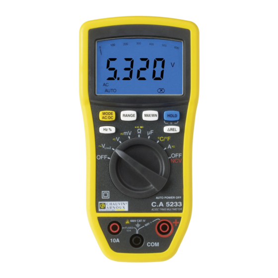
Français 1. PRÉSENTATION Le C.A 5233 est un multimètre numérique TRMS, portatif et autonome, spécialement conçu pour regrouper en un seul appareil les différentes fonctions de mesure des grandeurs électriques suivantes: Voltmètre en courant alternatif à basse impédance d'entrée (mesure de tensions en électricité... -
Page 7: L'afficheur
Français Voir § Rep. Désignation Afficheur Touches de fonction Commutateur Bornes 1.1 L’AFFICHEUR L’afficheur permet : Un affichage de type analogique du paramètre mesuré grâce au bargraphe, associé à l’affichage digital sur 6000 points. Une lecture confortable des informations grâce au rétro- éclairage de l’écran. - Page 8 Français Voir § Rep. Fonction Bargraphe Affichage (valeurs et unités de mesure) Nature de la mesure (alternatif ou continu) 3.2.1 3.2.2 Mode automatique de sélection du calibre de mesure Indicateur de pile usagée 3.1.3 Test de continuité sonore Test de diode 3.1.4 Affichage des modes sélectionnés 3.2.1...
-
Page 9: Les Touches
Français Ampère Ω Préfixe nano- µ Préfixe micro- Préfixe milli- Préfixe kilo- Préfixe méga- Test de continuité sonore Test de diode Mode Non Permanent (arrêt automatique activé) Indicateur de pile usagée 1.1.2 Dépassement des capacités de mesure (O.L.) Le symbole O.L. (Over Load) s’affiche quand le signal mesuré dépasse les capacités du calibre de l’appareil. -
Page 10: Le Commutateur
Français Rep. Fonction Voir § Sélection du type de mesure (AC ou DC), 3.2.1 , °C, °F ou . Activation ou désactivation de l’arrêt automatique de l’appareil au démarrage Sélection manuelle du calibre de mesure. 3.2.2 Activation ou désactivation du mode MAX/MIN Maintien de l’affichage de la valeur mesurée. -
Page 11: Les Bornes
Français Mesure de tension en AC ou DC (mV) 3.1.1 Mesure de résistance 3.1.2 Test de continuité 3.1.3 Test de diode 3.1.4 Mesure de capacité 3.1.5 Mesure de température en °C ou °F 3.1.6 Mesure d’intensité en AC ou DC 3.1.7 3.1.8 NCV (Non Contact Voltage) + Mode OFF... -
Page 12: Utilisation
Français 2. UTILISATION 2.1 PREMIÈRE UTILISATION Placez la pile fournie avec l’appareil comme suit : A l’aide d’un tournevis, dévissez les quatre vis a, b, c et d de la trappe (rep.1) situées à l’arrière du boîtier ; Placez la pile dans son logement (rep.2) en respectant les polarités ;... -
Page 13: La Béquille
Français 2.4 LA BÉQUILLE Deux positions de béquille sont possibles, soit accrocher le multimètre (position 1), soit le poser sur un support en position inclinée (position 2). Pour changer la position de la béquille, procédez comme suit : Positon positionnez Position 2 : positionnez la béquille vers le haut : béquille vers le bas :... -
Page 14: Fonctions
Français 3. FONCTIONS 3.1 FONCTIONS DU COMMUTATEUR Pour accéder aux fonctions du commutateur, placez le commutateur sur 3.1.1 Mesure de tension L’appareil mesure : La tension alternative en basse impédance d’entrée (V LOWZ La tension continue (DC) ; ... - Page 15 Français Placez les pointes de touche aux bornes du composant ou du circuit à mesurer ; La valeur de la résistance mesurée s’affiche à l’écran. 3.1.3 Test de continuité avec Buzzer Attention : toutes les mesures de continuité doivent se faire hors-tension.
-
Page 16: Mesure De Capacit
Français s’affiche ; Appuyez deux fois sur . Le symbole Branchez le cordon noir sur la borne COM et le cordon rouge sur « + » ; Placez les pointes de touche aux bornes du composant ; Sens direct La valeur de la tension développée s’affiche à l’écran. 3.1.5 Mesure de capacité... - Page 17 Français 3.1.6 Mesure de température Pour mesurer la température, procédez comme suit : Positionnez le commutateur sur pour sélectionner l’unité de l’échelle de Appuyez sur température (°C ou °F) ; Remarque : l’unité affichée par défaut est le °C. Branchez l’adaptateur pour sonde de température (rep.1) aux bornes COM et «...
-
Page 18: Fonctions Des Touches
La valeur de l’intensité mesurée s’affiche à l’écran. 3.1.8 Non Contact Voltage NCV Positionnez le commutateur sur Approchez le C.A 5233 (zone de détection NCV) du (des) conducteur(s) potentiellement sous tension (présence de phase) ; Si présence de tension réseau de 230V (modèle Europe), le rétro-éclairage s’allume en rouge ;... - Page 19 Français Chaque appui… … permet de changer la nature de la mesure : AC ou DC. Court de sélectionner les modes test de continuité ou test de diode d’afficher température degré Celsius (°C) ou en degré Fahrenheit (°F). 3.2.2 Touche Cette touche permet de choisir manuellement un calibre de mesure.
- Page 20 Français Chaque appui … … permet de appui court activer la mémorisation MAX/MIN. court à chaque appui, visualiser successivement la valeur MAX, MIN et courante. Remarque : la grandeur MAX est affichée par défaut. Long sortir du mode (> 2 sec) 3.2.4 Touche Cette touche permet de maintenir l’affichage de la valeur...
- Page 21 Français Touche 3.2.6 Cette touche permet d’afficher la valeur relative à partir d’une référence mémorisée lors de l’appui sur la touche. Par exemple, si la valeur mémorisée lors de l’appui sur la touche = 10 V, la valeur courante étant 11,5 V, l’affichage en mode relatif sera de 11,5 –...
-
Page 22: Caractéristiques
Français 4. CARACTÉRISTIQUES 4.1 CONDITIONS DE RÉFÉRENCE Grandeurs d’influence Conditions de référence Température : 23 °C ± 2 °C Humidité relative : 45 % à 75 % Tension d’alimentation : 8,5 V ± 0,5 V 4.2 CARACTÉRISTIQUES AUX CONDITIONS DE RÉFÉRENCE L’incertitude est exprimée en x % de la lecture + y point(s), de 10% à... - Page 23 Français 4.2.2 Tensions alternatives L’impédance d’entrée est de 10 M. mV AC True RMS Incertitude () Incertitude () Gamme Résolution 60 Hz à 1 kHz 45 Hz à 60 Hz 60 mV 0,01 mV 2 % + 12 pts 2,5 % + 12 pts 2 % + 3 pts 600 mV...
- Page 24 Français 4.2.4 Fréquence (V AC ou A AC) Gamme Résolution Incertitude () Sensibilité 10 à 3000 Hz 0,01 Hz 0,5 % 15 V RMS 4.2.5 Duty Cycle Gamme Résolution Incertitude () Fréquence 0,1 à 99,9 % 0,1 % 1,2 % + 2 pts 5 Hz à...
- Page 25 Français 4.2.9 Capacité Gamme Résolution Incertitude () 40 nF 0,01 nF 400 nF 0,1 nF 4 μF 0,001 μF 3,5 % + 4 pts 40 μF 0,01 μF 400 µF 0,1 µF 1000 µF 1 µF 5 % + 5 pts 4.2.10 Température (thermocouple de type K) L’incertitude est donnée sans le thermocouple K.
-
Page 26: Conditions D'environnement
Français 4.3 CONDITIONS D’ENVIRONNEMENT Conditions d’environnement en utilisation en stockage Température : 0 °C à +50 °C -20 °C à +70 °C Humidité relative (HR) : 90 % à 40 °C 50 % à 60 °C 4.4 CARACTÉRISTIQUES CONSTRUCTIVES Dimension : H 155 x L 75 x P 55 mm Masse : 320 g (avec la pile et le fusible) -
Page 27: Variations Dans Le Domaine D'utilisation
Français 4.7 VARIATIONS DANS LE DOMAINE D’UTILISATION Grandeur d’influence Plage d’influence Influence V AC : 0,5%L/10°C Température 0°C à + 50°C mV DC : 0,5%L/10°C Ω (R>20 MΩ) : 0,5%L/10°C µF (C>50 µF) : 5%L/10°C V AC : 10%L + 1pt Fréquence 1 à... -
Page 28: Remplacement Du Fusible
Tél. : 02 31 64 51 55 - Fax : 02 31 64 51 72 5.5 RÉPARATION Pour les réparations sous garantie et hors garantie, contactez votre agence commerciale Chauvin Arnoux la plus proche ou votre centre technique régional Manumesure qui établira un dossier de retour et vous communiquera la procédure à suivre. -
Page 29: Garantie
Des dommages dus à des chocs, chutes ou inondations. 7. POUR COMMANDER Le C.A 5233 Le multimètre est livré avec : 1 paire de cordons pointe de touche, rouge et noir 1 pile 9 V alcaline ... - Page 30 English PRECAUTIONS FOR USE This device complies with safety standard IEC-61010-1 for voltages up to 600V in category IV, at an altitude below 2000m, indoors, with a pollution level of not more than 2. Failure to observe the safety instructions may cause an electric shock, fire, explosion, or destruction of the instrument and of the installations.
- Page 31 English MEASUREMENT CATEGORIES Definitions of the measurement categories according to standard IEC 61010-1: CAT I: Circuits not directly connected to the network and specially protected. Example: protected electronic circuits. CAT II: Circuits directly connected to the low-voltage installation. Example: power supply to household electrical appliances and portable tools.
- Page 32 English Thank you for purchasing a C.A. 5233 multimeter. For best results from your device: Read this user manual attentively; Observe the precautions for its use. Meaning of the symbols used on the instrument: Risk of danger. The operator agrees to refer to these instructions whenever this danger symbol appears.
- Page 33 English CONTENTS 1. PRÉSENTATION..............34 1.1 THE DISPLAY UNIT ............35 1.2 THE KEYS ................. 37 1.3 THE SWITCH ..............38 1.4 THE TERMINALS ............... 39 2. USE ..................40 2.1 FIRST USE................. 40 2.2 POWERING UP THE MULTIMETER ........40 2.3 POWERING DOWN THE MULTIMETER ......
-
Page 34: Présentation
English 1. PRESENTATION The C.A 5233 is a TRMS digital multimeter, specially designed to combine in a single instrument the various functions and measurements of the following electrical quantities: voltmeter with input impedance (voltage measurements in the fields of electricity and electrical engineering);... -
Page 35: The Display Unit
English See § Item Designation Display unit Function keys Switch Terminals 1.1 THE DISPLAY UNIT The display unit allows : An analog display of the parameter measured, in the form of a bargraph, associated with a 6,000-point digital display. ... - Page 36 English See § Item Function Bargraph Display (values and units of measurement) Nature of the measurement (AC or DC) 3.2.1 Automatic measurement range selection mode 3.2.2 Low battery indicator Audible continuity test 3.1.3 Diode test 3.1.4 Display of the modes selected 3.2.1 Non-Permanent Mode : automatic switching off of the device activated...
-
Page 37: The Keys
English Ω Prefix, nano- µ Prefix, micro- Prefix, milli- Prefix, kilo- Prefix, Mega- Audible continuity test Diode test Non-Permanent Mode (automatic switching off activated) Low battery indicator 1.1.2 Overshoot of measurement capabilities (O.L.) The O.L. (Over Load) symbol is displayed when the signal measured exceeds the range of the device. -
Page 38: The Switch
English Item Function See § Selection of the type of measurement (AC or 3.2.1 DC), , °C, °F or . Activation or de- activation of the automatic switching off of the device at start-up. Manual selection of the measurement range. 3.2.2 Activation or de-activation of the MAX/MIN mode. -
Page 39: The Terminals
English Item Function See § OFF mode – Powers down the multimeter voltage measurement input 3.1.1 impedance (V LowZ AC or DC voltage measurement (V) 3.1.1 AC or DC voltage measurement (mV) 3.1.1 Resistance measurement 3.1.2 Continuity test 3.1.3 Diode test 3.1.4 Capacitance measurement 3.1.5... -
Page 40: Use
English 2. USE 2.1 FIRST USE Insert the battery provided with the instrument as follows: Using a screwdriver, unscrew the four screws (a, b, c, and d) holding the cover (item 1) on the back of the housing; Place the battery in its compartment (item 2); watch out for the polarity;... -
Page 41: The Prop
English 2.4 THE PROP The prop can be placed in either of two positions according to how it is to be used: to suspend the multimeter from a hook (position 1) or to stand it in an inclined position on a support (position 2). -
Page 42: Functions
English 3. FUNCTIONS 3.1 FUNCTIONS OF THE SWITCH To access to the functions of the switch, set the switch to 3.1.1 Voltage measurement The instrument measures: the AC voltage at low input impedance (VLowZ); direct voltages (DC); alternating voltages (AC). - Page 43 English The measured resistance is displayed on screen. 3.1.3 Continuity test with buzzer Attention: all continuity measurements must be made in the absence of any voltage. To test electrical continuity, proceed as follows: Set the switch to Press . The symbol is displayed ;...
-
Page 44: Capacitance Measurement
English Press twice. The symbol is displayed ; Connect the black lead to the COM terminal and the red lead to “+”; Place the contact tips on the terminals of the component; Forward direction The voltage across the terminals of the component is displayed on screen. -
Page 45: Temperature Measurement
English 3.1.6 Temperature measurement To measure the temperature, proceed as follows: Set the switch to to select the temperature unit and scale (°C or Press °F) ; Remark: the default is °C. Connect the temperature probe adapter (item 1) to the COM and “+”... -
Page 46: Functions Of The Keys
English The measured current is displayed on screen. 3.1.8 Non-Contact Voltage NCV Set the switch to Move the C.A 5231 (NCV detection zone) close to the potentially live conductor(s) (presence of phase); If a network voltage of 230V is present (Europe model), the back-lighting lights red;... - Page 47 English …serves to Each press of this length… Change the nature of the measurement AC or DC. short Select the continuity test or diode test mode. To display the temperature in degrees Celsius (°C) or in degrees Fahrenheit (°F). 3.2.2 This key is used to choose a measurement range manually.
- Page 48 English …serves to Each press of this length… short Activate MAX/MIN storage. short At each press, to view in turn the MAX, MIN, and current value. Remark: the MAX value is displayed as default. Long Exit from the mode. (> 2 sec) 3.2.4 This key is used to hold the display of the measured value, and to activate/deactivate the backlighting of the screen.
- Page 49 English 3.2.6 This key is used to display the value relative to a reference stored when the key was pressed. For example, if the value stored when the key was pressed = 10V and the current value is 11.5V, the display in relative mode will be 11.5 - 10 = 1.5V.
-
Page 50: Characteristics
English 4. CHARACTERISTICS 4.1 REFERENCE CONDITIONS Quantities of influence Reference conditions Temperature : 23 °C ± 2 °C Relative humidity : 45 % to 75 % Supply voltage : 8.5 V ± 0.5 V 4.2 CHARACTERISTICS AT THE REFERENCE CONDITIONS The uncertainty is expressed in the form x% of the reading + y counts, from 10% to 100% of each measurement range. - Page 51 English 4.2.2 Alternating voltages The input impedance is 10 M. mV AC True RMS Uncertainty () Uncertainty () Range Resolution 60 Hz to 1 kHz 45 Hz to 60 Hz 60 mV 0.01 mV 2 % + 12 cts 2.5 % + 12 cts 2 % + 3 cts 600 mV...
-
Page 52: Continuity Test
English 4.2.5 Duty Cycle Range Resolution Uncertainty () Frequency 0.1 to 99.9 % 0.1 % 1.2 % + 2 cts 5 Hz to 150 kHz 4.2.6 Resistance Range Resolution Uncertainty () 600 Ω 0.1 Ω 2 % + 2 cts 6 kΩ... -
Page 53: Environmental Conditions
English 4.2.10 Temperature (type K thermocouple) The uncertainty does not include the K thermocouple. Range Resolution Uncertainty () 2 % + 5°C - 20 to 760 °C 1°C 2 % + 9°F - 4 to 1400 °F 1°F 4.2.11 Max/Min Capture time: 400 ms Add an uncertainty of ±... -
Page 54: Characteristics Of Construction
English 4.4 CHARACTERISTICS OF CONSTRUCTION Dimension : H 155 x W 75 x D 55 mm Weight : 320 g (with the battery and the fuse) Bargraph : 61 segments, refresh interval 30 ms Measurement 3 times per second acquisition: 4.5 POWER SUPPLY Power supply : 9 V LF22/6LR61 battery... -
Page 55: Maintenance
This instrument should be checked at least once a year. For checking and calibration, contact one of our accredited metrology laboratories (information and contact details available on request), at our Chauvin Arnoux subsidiary or the branch in your country. 55 - 138... -
Page 56: Repair
Damage caused by shocks, falls, or floods. 7. TO ORDER The C.A 5233 The multimeter is delivered with : 1 pair of leads, red and black 1 9V alkaline battery 1 temperature probe (type K thermocouple) ... - Page 57 Deutsch BEDIENUNGSHINWEISE Dieses Gerät entspricht der Sicherheitsnorm IEC-61010-1 bei Spannungen 600V KAT IV auf bis zu 2000 m Höhe und in Innenräumen, bis zu einem Verschmutzungsgrad 2. Sicherheitsanweisungen müssen unbedingt beachtet werden, weil sonst Stoßspannung, Brand, Explosion oder Zerstörung des Geräts und der Anlagen drohen. ...
- Page 58 Deutsch MESSKATEGORIE Definition der Messkategorien gemäß IEC 61010-1: CAT I: Stromkreise, die nicht direkt mit dem Stromnetz verbunden sind oder geschützt sind. Beispiel: geschützte Stromkreise. CAT II: Stromkreise an Niederspannungsanlagen. Beispiel: Stromversorgung Haushaltsgeräten oder tragbaren Elektrowerkzeugen. CAT III: Stromversorgungskreise innerhalb der Haus- oder Gebäudeinstallation.
- Page 59 Deutsch Sie haben ein C.A. 5233 Multimeter erstanden, wir danken Ihnen für Ihr Vertrauen. Für die Erlangung eines optimalen Betriebsverhaltens Ihres Gerätes: Lesen Sie bitte diese Betriebsanleitung aufmerksam durch und; Beachten Sie bitte die Anwendungshinweise. Bedeutung der Gerätesymbole: Gefahr! Sobald dieses Gefahrenzeichen auftritt, ist der Bediener verpflichtet, die Anleitung zu Rate zu ziehen.
- Page 60 Deutsch INHALT 1. VORSTELLUNG ..............61 1.1 ANZEIGE ................62 1.2 TASTEN ................64 1.3 SCHALTER ................ 65 1.4 BUCHSEN................66 2. VERWENDUNG ..............67 2.1 ERSTE SCHRITTE ............. 67 2.2 MULTIMETER-INBETRIEBNAHME ........67 2.3 MULTIMETER ABSCHALTEN ..........67 2.4 DER STANDBÜGEL ............68 3.
-
Page 61: Vorstellung
Kapazität; Thermometer in °C oder °F bei Messung oder Linearisierung der Lastspannung an den Buchsen eines Thermoelement Type K; Berührungsfreie Erfassung Netzspannung (NCV- Funktion Vorhandsein von Phasen). Erfassungsbereich NCV Abb. 1 : Multimeter C.A 5233 61 - 138... -
Page 62: Anzeige
Deutsch Siehe Abs. Bezeichnung Anzeige Funktionstasten Drehschalter Buchsen 1.1 ANZEIGE Die Anzeige ermöglicht : Eine Analog-Anzeige dank einer Balkenanzeige, sowie eine Digitalanzeige mit 6000 Digits. Ein bequemes Ablesen der Informationen dank der Hintergrundbeleuchtung der Anzeige. Abb. 2 : Anzeige 62 - 138... - Page 63 Deutsch Siehe Funktion Abs. § Balkenanzeige Anzeige (Werte und Messeinheiten) Messart (AC oder DC) 3.2.1 Automatische Messbereichseinstellung 3.2.2 Anzeige bei geringem Batterieladestand Akustische Durchgangsprüfung 3.1.3 Diodenprüfung 3.1.4 Anzeige des ausgewählten Modus 3.2.1 Nicht-Dauerbetriebmodus: Stromsparmodus (autom. Abschalten des Gerätes) aktiviert 1.1.1 Anzeigesymbole Folgende Anzeigesymbole werden verwendet: Symbole...
-
Page 64: Tasten
Deutsch Ω Vorsilbe für „Nano“ Vorsilbe für „Mikro“ µ Vorsilbe für „Milli-“ Vorsilbe für „Kilo-“ Vorsilbe für „Mega-“ Akustische Durchgangsprüfung Diodenprüfung Nicht-Dauerbetriebsmodus (Abschaltautomatik) Anzeige bei geringem Batterieladestand 1.1.2 Überschreitung der Messkapazität (O.L) Das Symbol O.L (Over Load) erscheint auf der Anzeige, wenn Messsignal Messbereichkapazität Gerätes... -
Page 65: Schalter
Deutsch Siehe Funktion Abs. Auswahl für die Messart (AC oder DC), 3.2.1 °C, °F oder . Aktivierung oder Deaktivierung der Abschaltautomatik des Gerätes beim Start. Manuelle Auswahl des Messbereiches. 3.2.2 Aktivierung oder Deaktivierung Modus MAX/MIN Hold-Modus des angezeigten Werts. Aktivierung oder Deaktivierung blauen... -
Page 66: Buchsen
Deutsch Siehe Funktion Abs. OFF – Multimeter ausschalten Messung von Wechselspannung in niedriger 3.1.1 Eingangsimpedanz (V LowZ Messen der AC- oder DC-Spannung (V) 3.1.1 Messen der AC- oder DC-Spannung (mV) 3.1.1 Messung des Widerstandes 3.1.2 Durchgangsprüfung 3.1.3 Diodenprüfung 3.1.4 Kapazitätsmessung 3.1.5 Temperaturmessung in °C oder °F 3.1.6... -
Page 67: Verwendung
Deutsch 2. VERWENDUNG 2.1 ERSTE SCHRITTE Legen Sie die mitgelieferte Batterie so ein: Mit einem Schraubendreher die vier Schrauben a, b, c und d des Batteriefachdeckels (Nr. 1) hinten am Gehäuse lösen; Die Batterie in das Gehäuse (Nr. 2) einlegen, Polarität beachten. -
Page 68: Der Standbügel
Deutsch 2.4 DER STANDBÜGEL Es gibt zwei Positionen für den Standbügel: Man kann das Multimeter daran aufhängen (Position 1), und man kann es schräg aufstellen (Position 2). Wechseln der Standbügelstellung wie folgt: Positon 1 : Legen Sie die Position 2 : Legen Sie die Standbügel nach oben: Standbügel nach unten: Hängevorric... -
Page 69: Funktionen
Deutsch 3. FUNKTIONEN 3.1 DREHSCHALTERFUNKTIONEN Direkter Zugriff auf die Funktionen oder über die jeweilige Drehschalterposition. 3.1.1 Spannungsmessungen Das Gerät misst: Die Wechselspannung niedriger Eingangsimpedanz LowZ DC-Spannung; AC-Spannung; Zum Spannungsmessen geht man wie folgt vor: Stellen Sie den Drehschalter auf oder ist das Gerät nur im AC-Modus;... - Page 70 Deutsch 3.1.2 Messung des Widerstandes Achtung: Widerstände dürfen nur spannungsfrei gemessen werden. Zum Messen des Widerstands geht man wie folgt vor: Stellen Sie den Drehschalter auf schwarzen Prüfdraht Buchse anschließen, den roten Prüfdraht an +; Die Prüfspitzen an den Buchsen des Prüfkreises bzw. Prüflings anbringen;...
- Page 71 Deutsch 3.1.4 Diodenprüfung Achtung: Alle Diodentest-Messungen müssen außer Spannung erfolgen. Für die Diodenprüfung geht man wie folgt vor: Stellen Sie den Drehschalter auf Drücken Sie zwei Mal auf . Das Symbol wird angezeigt. schwarzen Prüfdraht Buchse anschließen, den roten Prüfdraht an +; Legen Sie die Prüfspitzen an die Komponentenbuchsen;...
- Page 72 Deutsch Der gemessene Kapazitätswert erscheint auf der Anzeige. 3.1.6 Temperaturmessung Zur Temperaturmessung geht man so vor: Stellen Sie den Drehschalter auf Auswahl der Einheit der Temperatur Drücken Sie auf (°C oder °F); Anmerkung: Die angezeigte Einheit ist °C (Voreinstellung). Schließen Sie den Adapter für Temperatursonde (Nr.1) an die Buchsen COM und „+“...
-
Page 73: Tastenfunktionen
Die gemessene Stromstärke erscheint auf der Anzeige. 3.1.8 Non Contact Voltage NCV Stellen Sie den Drehschalter auf Nähern Sie das C.A 5233 (Erkennungszone NCV) dem/den möglicherweise spannungsführenden Leiter/n (Vorhandensein von Phasen); Beim Vorhandensein von 230V Netzspannung (für Europa-Modell), leuchtet die Hintergrundbeleuchtung rot auf;... - Page 74 Deutsch Standardmäßig ist die Abschaltautomatik aktiviert, das Symbol wird angezeigt. Hinweis: Der DC-Modus wird standardmäßig aktiviert. …geschieht Folgendes: Mit jedem Tastendruck… Messart ändern: AC oder DC. Kurz Prüfmodus für Durchgang bzw. Diode wählen. Die Temperatur in Celsius (°C) oder in Fahrenheit (°F) anzeigen.
- Page 75 Deutsch …geschieht Folgendes: Mit jedem Tastendruck… 1. kurzes Drücken Abspeichern MAX/MIN aktivieren. jedem Drücken, zeigen abwechselnd die aktuellen / MAX / MIN Wert an. kurz Anmerkung: Die MAX-Größe wird standardmäßig angezeigt. Lang Modus verlassen. (> 2 sec) 3.2.4 Taste Mit dieser Taste kann die Anzeige des gemessenen Werts gehalten werden, und außerdem die Hintergrundbeleuchtung der Anzeige aktiviert bzw.
-
Page 76: Eigenschaften
Deutsch Taste 3.2.6 Beim Drücken dieser Taste wird der relative Wert einer gespeicherten Referenz angezeigt werden. Zum Beispiel: Wenn der gespeicherte Wert beim Drücken der Taste = 10V und der aktuelle Wert 11,5V ist, beträgt die Anzeige im relativen Modus 11,5-10 = 1,5V. Hinweis: der Autorange-Modus wird deaktiviert. - Page 77 Deutsch 4.2.1 DC-Spannung Die Eingangsimpedanz ist 10MΩ mV DC Bereich Auflösung Abweichungen () 60 mV 0,01 mV 1 % + 12 pkte 600 mV 0,1 mV 0,6 % + 2 pkte V DC Bereich Auflösung Abweichungen () 600 mV 0.1 mV 0.6 % + 2 pkte 0.001 V...
- Page 78 Deutsch 4.2.3 AC-Spannung mit niedriger Impedanz (V AC LowZ True RMS) Die Eingangsimpedanz ist 270kΩ Durch eine niedrige Eingangsimpedanz können die Störspannungen aus dem Versorgungsnetz ausgeglichen werden. Dadurch kann eine Wechselspannung ohne Fehler gemessen werden. Abweichungen Bereich Auflösung () 45 Hz à 60 Hz 0,001 V 2 % + 10 pkte * In Anwendung der Sicherheitsvorschriften, 1000V Bereich ist...
- Page 79 Deutsch 4.2.7 Durchgangsprüfung Bereich Auflösung Abweichungen Messstrom Signallaut 600 Ω 0,1 Ω < 0,35 mA < 20 Ω 4.2.8 Diodenprüfung Abweichungen Bereich Auflösung Leerspannung Messstrom () 2,8 V 0,001 V 2% + 5 pkte < 2,8 V < 0,9 mA 4.2.9 Kapazität Bereich...
-
Page 80: Umweltbedingungen
Deutsch 4.2.12 Gleichströme (10 A DC) Abweichungen Bereich Auflösung Schutz () 0,001 A Flinke Sicherung 1,5 % + 3 pkte F10 A/600 V/50 kA 10 A* 0,01 A 6,3x32 *15 A für max. 60 Sekunden 4.2.13 Wechselströme (10 A AC) Abweichungen Bereich Auflösung... -
Page 81: Konformität Mit Internationalen Normen
Deutsch 4.6 KONFORMITÄT MIT INTERNATIONALEN NORMEN Anwendung der Sicherheitsvorschriften gemäß EN 61010-1. Elektrische Sicherheit: 1000V CAT III - 600V CAT IV. Verschmutzungsgrad 2. Schutzisoliert. Elektromagnetische Gemäß EN-61326-1 Verträglichkeit Wohngebiet (EMV): Schutzgrad Hülle Freier Fall: 1m (gemäß Norm IEC-68-2-32) Schutzgrad der Hülle IP 54 nach EN-60529 4.7 SCHWANKUNGEN IM EINSATZBEREICH Einflussgröße... -
Page 82: Batteriewechsel
Überprüfung dieses Gerätes empfohlen. Für Überprüfung und Kalibrierung wenden Sie sich bitte an unsere zugelassenen Messlabors (Auskunft und Adressen auf Anfrage), bzw. an die Chauvin Arnoux Niederlassung oder den Händler in Ihrem Land. 5.5 REPARTUR Senden Sie das Gerät bei Reparaturen innerhalb und außerhalb der Garantie an die Chauvin Arnoux Niederlassung... -
Page 83: Garantie
Anleitung aufgeführte Verwendungszwecke; Schäden durch Stöße, Herunterfallen, Überschwemmung. 7. BESTELLANGABEN C.A 5233 Lieferumfang des Multimeters: 1 Satz Prüfdrähte, rot und schwarz 1 Alkali-Akku 9V 1 Temperatursonde (Thermoelement Type K) 1 Adapter für Temperatursonde Type K ... - Page 84 Italiano PRECAUZIONI D’USO Questo strumento è conforme alla norma di sicurezza IEC- 61010-1 per tensioni di 600V in categoria IV ad una altitudine inferiore a 2000 m e all’interno, con un grado d’inquinamento pari a 2 (Massimo). Il mancato rispetto delle consegne di sicurezza può causare un rischio di shock elettrico, incendio, esplosione, distruzione dello strumento e degli impianti.
- Page 85 Italiano CATEGORIE DI MISURA Definizione delle categorie di misura secondo la norma IEC- 61010-1: CAT I: Circuiti non collegati direttamente alla rete e particolarmente protetti. Esempio: circuiti elettronici protetti. CAT II: Circuiti direttamente collegati all'impianto a bassa tensione. Esempio: alimentazione d’apparecchi elettrodomestici d’attrezzatura portatile.
- Page 86 Italiano Avete appena acquistato un multimetro C.A. 5233 e vi ringraziamo della vostra fiducia. Per ottenere dal vostro apparecchio le migliori prestazioni: Leggere attentamente questo modo d’uso, Rispettare le precauzioni d’uso. Significato dei simboli utilizzati sull’apparecchio: Rischio di pericolo. L'operatore s'impegna a consultare il presente libretto ogni volta che incontra questo simbolo di pericolo.
- Page 87 Italiano INDICE 1. PRESENTAZIONE ..............88 1.1 IL DISPLAY ................ 89 1.2 I TASTI ................91 1.3 IL COMMUTATORE ............92 1.4 I MORSETTI ............... 93 2. UTILIZZO ................94 2.1 PRIMO UTILIZZO ............... 94 2.2 MESSA IN SERVIZIO DEL MULTIMETRO ......94 2.3 ARRESTO DEL MULTIMETRO ..........
-
Page 88: Presentazione
Italiano 1. PRESENTAZIONE C.A 5233 è un multimetro digitale TRMS, portatile e autonomo, appositamente progettato per raggruppare in un solo strumento le varie funzioni di misura delle seguenti grandezze elettriche: Voltmetro in corrente alternata a bassa impedenza d'entrata (misura di tensioni d’elettricità e d’elettrotecnica);... -
Page 89: Il Display
Italiano Consultare § Rif. Descrizione Display Tasti di funzione Commutatore Morsetti 1.1 IL DISPLAY Il display permette : Una visualizzazione di tipo analogico del parametro misurato grazie al bargraph, associato alla visualizzazione digitale su 6000 punti. Una confortevole lettura delle informazioni grazie alla retroilluminazione dello schermo. - Page 90 Italiano Consultare § Rif. Funzione Bargraph Visualizzazione (valori e delle unità di misura) Natura della misura (alternata o continua) 3.2.1 3.2.2 Modo automatico di selezione del calibro di misura Indicatore di pila usata Test de continuità sonore 3.1.3 Test diodo 3.1.4 Visualizzazione dei modi selezionati 3.2.1...
-
Page 91: I Tasti
Italiano Ampere Ω Prefisso nano- µ Prefisso micro- Prefisso milli- Prefisso kilo- Prefisso méga- Test di continuà sonora Test diodo Modo Non Permanent (arresto automatico attivato) Indicatore di pila usata 1.1.2 Superamento delle capacità di misura (O.L.) Il simbolo O.L (Over Load) appare quando il segnale applicato supera le capacità... -
Page 92: Il Commutatore
Italiano Rif. Funzione Consultare § Selezione del tipo di misura (AC o 3.2.1 DC), , °C, °F o . Attivazione o dell’arresto automatico disattivazione dell’apparecchio all’avviamento. Selezione manuale del calibro di misura. 3.2.2 Attivazione o disattivazione del modo MAXI/MINI Mantenimento della visualizzazione del valore misurato. -
Page 93: I Morsetti
Italiano Rif. Funzione Consultare § Modo OFF – Arresto del multimetro Misura di tensione alternata in bassa 3.1.1 impedenza d'entrata (V LowZ Misura di tensione in AC o in DC (V) 3.1.1 Misura di tensione in AC o in DC (mV) 3.1.1 Misura di resistenza 3.1.2... -
Page 94: Utilizzo
Italiano 2. UTILIZZO 2.1 PRIMO UTILIZZO Inserite la pila fornita con lo strumento come segue: Mediante un cacciavite, svitate le quattro viti a, b, c e d dello sportello (rif. 1) posto nel retro della scatola; Inserite la pila nel suo alloggiamento (rif. 2) rispettando la polarità;... -
Page 95: Il Puntello
Italiano 2.4 IL PUNTELLO Il puntello può assumere due posizioni: per l’aggancio del multimetro (posizione 1), o per posarlo su un supporto in posizione inclinata (posizione 2). Per cambiare la posizione del puntello, procedete come segue: Posizione 1 : posizionate il Posizione 2 : posizionate il puntello verso l’alto : puntello verso il basso :... -
Page 96: Funzioni
Italiano 3. FUNZIONI 3.1 FUNZIONI DEL COMMUTATORE Per accedere alle funzioni oppure posizionate il commutatore sulla funzione scelta. 3.1.1 Misura di tensione Lo strumento misura : la tensione alternata in bassa impedenza d'ingresso (V LowZ la tensione continua (DC); ... - Page 97 Italiano Posizionate le punte di contatto sui morsetti del componente o del circuito da misurare; Il valore della resistenza misurata si visualizza allo schermo. 3.1.3 Test di continuità con cicalino Attenzione : tutte le misure di continuità vanno effettuate fuori tensione.
- Page 98 Italiano Premete due volte . Appare il simbolo Allacciate il cordone nero al morsetto COM e il cordone rosso a “+”; Posizionate le punte di contatto sui morsetti del componente; Senso diretto Il valore della tensione sviluppata si visualizza allo schermo. 3.1.5 Misura di capacità...
- Page 99 Italiano 3.1.6 Misura di temperatura Per misurare la temperatura, procedete come segue: Posizionate il commutatore su per selezionare l’unità della scala termica Premete (°C o °F) ; Osservazione : l’unità visualizzata per difetto è in °C. Allacciate l’adattatore per sonda di temperatura (rif. 1) ai morsetti COM e “+”...
-
Page 100: Funzioni Dei Tasti
Italiano Il valore dell’intensità misurata si visualizza allo schermo. 3.1.8 Non Contact Voltage NCV Posizionate il commutatore su Avvicinate il C.A5233 (zona di rivelazione NCV) al o ai conduttori potenzialmente sotto tensione (presenza di fase); Se presenza di tensione rete di 230V (modello Europeo), la retroilluminazione si accende in rosso;... - Page 101 Italiano Ogni pressione… …permette di cambiare la natura della misura: AC oppure DC. breve selezionare i modi test di continuità o test diodo visualizzare la temperatura in gradi Celsius (°C) oppure Fahrenheit (°F). 3.2.2 Tasto Questo tasto permette di scegliere manualmente un calibro di misura.
- Page 102 Italiano …permette di Ogni pressione… pressione attivare la memorizzazione breve MAXI/MINI. ogni pressione, visualizzare successivamente il valore MAXI, MINI e corrente. breve Osservazione: la grandezza MAXI si visualizza per difetto. Lunga (> 2 sec) uscire dal modo 3.2.4 Tasto Questo tasto permette di mantenere la visualizzazione del valore misurato;...
-
Page 103: Caratteristiche
Italiano Tasto 3.2.6 Questo tasto permette di visualizzare il valore relativo mediante una referenza memorizzata quando si preme il tasto. Per esempio, se il valore memorizzato quando si preme il tasto = 10V, il valore corrente è 11,5V, la visualizzazione in modo relativo sarà... - Page 104 Italiano 4.2.1 Tensioni continue La impedenza d’entrata è de 10MΩ mV DC Gamma Risoluzione Incertezza () 60 mV 0,01 mV 1 % + 12 punti 600 mV 0,1 mV 0,6 % + 2 punti V DC Gamma Risoluzione Incertezza () 600 mV 0.1 mV...
- Page 105 Italiano 4.2.3 Tensioni alternate in bassa impedenza (V AC LowZ True RMS) La impedenza d’entrata è de 270kΩ Una bassa impedenza d’ingresso permette di affrancarsi dalle tensioni parassite dovute alla rete d’alimentazione, e di misurare una tensione alternata minimizzando gli errori. Gamma Risoluzione Incertezza ()
- Page 106 Italiano 4.2.7 Test di continuità Corrente di Gamma Risoluzione Incertezza misura Segnale sonoro 600 Ω 0,1 Ω < 0,35 mA < 20 Ω 4.2.8 Test diodo Tensione in Correnre di Gamma Risoluzione Incertezza () circuito aperto misura 2,8 V 0,001 V 2% + 5 punti <...
-
Page 107: Condizioni Ambientali
Italiano 4.2.12 Correnti continui (10 A DC) Gamma Risoluzione Incertezza () Protezione 0,001 A Fusibile rapido 1,5 % + 3 punti F10 A/600 V/50 kA 10 A* 0,01 A 6,3x32 *15 A per 60 secondi (massimo). 4.2.13 Correnti alterni (10 A AC) Gamma Risoluzione Incertezza () -
Page 108: Conformitá Alle Norme Internazionali
Italiano 4.6 CONFORMITÁ ALLE NORME INTERNAZIONALI Applicazione delle regole di sicurezza secondo la norma EN 61010-1. Sicurezza elettrica : 1000V CAT III-600V CAT IV. Grado d’inquinamento 2. Doppio isolamento. Conforme alla norma EN-61326-1 Compatibilità elettromagnetica: Ambiente residenziale Resistenza Caduta libera: 1 m (secondo la norma IEC- meccanica : 68-2-32) Grado di protezione... -
Page 109: Sostituzione Della Pila
Per le verifiche e le calibrazioni, rivolgetevi ai nostri laboratori di metrologia accreditati (informazioni e recapiti su richiesta), alla filiale Chauvin Arnoux del Vostro paese o al vostro agente. 5.5 RIPARAZIONE Per qualsiasi intervento da effettuare in o fuori garanzia, si prega d’inviare lo strumento al vostro distributore. -
Page 110: Garanzia
Danni dovuti ad urti, cadute o a fortuito contatto con l’acqua. 7. PER ORDINARE C.A 5233 Il multimetro è consegnato con : 1 paio di cordoni punta di contatto, rosso e nero 1 pila 9V alcalina ... - Page 111 Español PRECAUCIONES DE USO Este instrumento cumple con la norma de seguridad IEC 61010-1 para tensiones de 600 V en categoría IV a una altitud inferior a 2.000 m y en interiores, con un grado de contaminación igual a 2 como máximo. El incumplimiento de las instrucciones de seguridad puede ocasionar un riesgo de descarga eléctrica, fuego, explosión, destrucción del instrumento e instalaciones.
- Page 112 Español CATEGORÍAS DE MEDIDA Definición de las categorías de medida según la norma IEC - 61010-1: CAT I: Circuitos no conectados directamente a la red y especialmente protegidos. Ejemplo: circuitos electrónicos protegidos. CAT II: Circuitos directamente conectados a la instalación de baja tensión.
- Page 113 Español Usted acaba de adquirir un multímetro C.A 5233 y le agradecemos su confianza. Para conseguir las mejores prestaciones de su instrumento: Lea detenidamente este manual de instrucciones, Respete las precauciones de uso. Significado de los símbolos utilizados en el instrumento: Riesgo de peligro.
- Page 114 Español ÍNDICE 1. PRESENTACIÓN ..............115 1.1 EL DISPLAY ..............116 1.2 LAS TECLAS ..............118 1.3 ELL CONMUTADOR ............119 1.4 LOS TERMINALES ............120 2. UTILIZACIÓN................ 121 2.1 PRIMERA UTILIZACIÓN ........... 121 2.2 PUESTA EN SERVICIO DEL MULTÍMETRO ...... 121 2.3 APAGADO DEL MULTÍMETRO .........
-
Page 115: Presentación
Español 1. PRESENTACIÓN El C.A 5233 es un multímetro digital TRMS, portátil y autónomo, especialmente diseñado para reunir en un único instrumento las diferentes funciones de medida de las siguientes magnitudes eléctricas: Voltímetro en corriente alterna de baja impedancia de entrada (medida de tensión en electricidad y electrotécnica);... -
Page 116: El Display
Español Véase § N° Descripción Display Teclas de función Conmutador Terminales 1.1 EL DISPLAY El display permite: Una visualización de tipo analógica del parámetro medido, gracias a la barra analógica, asociada a la visualización digital de 6.000 puntos. Una lectura cómoda de la información gracias a la retroiluminación de la pantalla. - Page 117 Español Véase § N° Función Barra analógica. Visualización (valores y unidades de medida). Naturaleza de la medida (alterna o continúa). 3.2.1 Modo automático de selección del rango de 3.2.2 medida. Indicador de pila gastada. Prueba acústica de continuidad. 3.1.3 Prueba de diodo. 3.1.4 Visualización de los modos deseleccionados.
-
Page 118: Las Teclas
Español Ω Ohmio Prefijo nano- µ Prefijo micro- Prefijo milli- Prefijo kilo- Prefijo mega- Prueba acústica de continuidad Prueba de diodo Modo No Permanente (auto apagado activado) Indicador de pila gastada 1.1.2 Rebasamiento de las capacidades de medida (O.L.) El símbolo O.L (Over Load) aparece cuando la señal medida rebasa las capacidades del rango del instrumento. -
Page 119: Ell Conmutador
Español N° Función Véase § Selección del tipo de medida (AC o DC), 3.2.1 °C, °F o . Activación o desactivación del auto apagado del instrumento al encenderlo. Cambio manual del rango de medida. 3.2.2 Activación o desactivación del modo MÁX./MÍN. Mantenimiento de la visualización del valor medido. -
Page 120: Los Terminales
Español Medida de tensión en AC o DC (mV) 3.1.1 Medida de resistencia 3.1.2 Prueba de continuidad 3.1.3 Prueba de diodo 3.1.4 Medida de capacidad 3.1.5 Medida de temperatura en °C o °F 3.1.6 Medida de intensidad en AC o DC 3.1.7 3.1.8 NCV (Non Contact Voltage) + Modo OFF... -
Page 121: Utilización
Español 2. UTILIZACIÓN 2.1 PRIMERA UTILIZACIÓN Coloque la pila suministrada con el instrumento como se indica a continuación: Con un destornillador, desatornille los cuatro tornillos a, b, c y d de la tapa (nº 1) situada en la parte posterior de la carcasa;... -
Page 122: El Soporte
Español 2.4 EL SOPORTE El soporte tiene dos posiciones, o bien colgar el multímetro (posición 1), o bien colocarlo sobre una superficie en posición inclinada (posición 2). Para cambiar la posición del soporte, proceda como se indica a continuación: Posición 1 : ponga el soporte Posición ponga hacia arriba. -
Page 123: Funciones
Español 3. FUNCIONES 3.1 FUNCIONES DEL CONMUTADOR Para acceder a las funciones del conmutador, posicione el conmutador 3.1.1 Medida de tensión El instrumento mide: la tensión alterna con baja impedancia de entrada (V LowZ la tensión continua (DC); ... - Page 124 Español Coloque las puntas de prueba a los terminales del componente o del circuito a medir. El valor de la resistencia medida aparece en pantalla. 3.1.3 Prueba de continuidad con zumbador Atención: todas las medidas de continuidad deben realizarse con el instrumento apagado. Para probar la continuidad eléctrica, proceda como se indica a continuación: Posicione el conmutador en...
- Page 125 Español Pulse dos veces. Aparece el símbolo Conecte el cable negro al terminal COM y el cable rojo al “+”; Coloque las puntas de prueba en los terminales del componente. Sentido directo El valor de la tensión desarrollada aparece en pantalla. 3.1.5 Medida de capacidad Atención: todas las medidas de capacidades deben realizarse...
- Page 126 Español 3.1.6 Medida de temperatura Para medir la temperatura, proceda como se indica a continuación: Posicione el conmutador en para seleccionar la unidad de la escala de Pulse temperatura (°C o °F); Observación: la unidad visualizada por defecto es el ºC. Conecte el adaptador para la sonda de temperatura (nº...
-
Page 127: Funciones De Las Teclas
El valor de la intensidad medida aparece en pantalla. 3.1.8 Non Contact Voltage NCV Posicione el conmutador en Acerque el C.A 5233 (zona de detección NCV) del (de los) conductor(es) potencialmente bajo tensión (presencia de fase). Si se detecta una tensión de red de 230 V (modelo Europeo), la retroiluminación se enciende en rojo;... - Page 128 Español Cada pulsación… …permite cambiar la naturaleza de la medida: AC o DC. seleccionar los modos prueba Corta continuidad o prueba de diodo visualizar la temperatura grado Celsius (°C) o en grado Fahrenheit (°F). 3.2.2 Tecla Esta tecla permite elegir manualmente un rango de medida. El rango define la amplitud de medida máxima que el instrumento puede efectuar.
- Page 129 Español …permite Cada pulsación… activar la memorización MÁX./MÍN. pulsación corta cada pulsación, visualizar sucesivamente el valor MÁX., MÍN. y corriente. corta Observación: la magnitud MÁX. se visualiza por defecto. Larga (> 2 sec) Salir del modo 3.2.4 Tecla Esta tecla permite mantener la visualización del valor medido, así...
-
Page 130: Características
Español Tecla 3.2.6 Esta tecla permite visualizar el valor relativo a partir de una referencia memorizada. Por ejemplo, si el valor memorizado cuando se pulsa la tecla = 10 V, el valor corriente siendo de 11,5 V, la visualización en modo relativo será... - Page 131 Español 4.2.1 Tensiones continuas La impedancia de entrada es de 10 MΩ. mV DC Rango Resolución Incertidumbre () 60 mV 0,01 mV 1 % + 12 ctas 600 mV 0,1 mV 0,6 % + 2 ctas V DC Rango Resolución Incertidumbre ()
- Page 132 Español 4.2.3 Tensiones alterna con baja impedancia (V AC LowZ True RMS) La impedancia de entrada es de 270 kΩ. Una baja impedancia de entrada permite librarse de las tensiones parásitas debidas a la red de alimentación y medir una tensión alterna minimizando los errores. Rango Resolución Incertidumbre ()
- Page 133 Español 4.2.7 Prueba de continuidad Corriente de Rango Resolución Incertidumbre medida Señal acústica 600 Ω 0,1 Ω < 0,35 mA < 20 Ω 4.2.8 Prueba de diodo Incertidumbre Tensión en circuito Corriente de Rango Resolución () abierto medida 2,8 V 0,001 V 2% + 5 pts <...
-
Page 134: Condiciones De Entorno
Español 4.2.12 Corriente continuas (10 A DC) Rango Resolución Incertidumbre () Protección 0,001 A Fusible rápido 1,5 % + 3 ctas F10 A/600 V/50 kA 10 A* 0,01 A 6,3x32 *15 A durante 60 segundos como máximo. 4.2.13 Corriente alternas (10 A AC) Rango Resolución Incertidumbre () -
Page 135: Conformidad Con Las Normas Internacionales
Español 4.6 CONFORMIDAD CON LAS NORMAS INTERNACIONALES Aplicación de las reglas de seguridad según la norma EN -61010-1. Seguridad eléctrica : 600V CAT-IV. Grado de contaminación 2. Doble aislamiento. Conforme a la norma EN -61326-1 Compatibilidad electromagnética : Entorno residencial Resistencia Caída libre: 1 m (según la norma IEC-68-2- mecánica :... -
Page 136: Mantenimiento
Le aconsejamos por lo menos una verificación anual de este instrumento. Para las verificaciones y calibraciones, póngase contacto nuestros laboratorios metrología acreditados (solicítenos información y datos), con la filial Chauvin Arnoux o con el agente de su país. 136 - 138... -
Page 137: Reparación
Daños debidos a golpes, caídas o inundaciones. 7. PARA PEDIDOS C.A 5233 Em multímetro se suministra con: 1 par de cables con punta de prueba, rojo y negro; 1 pila alcalina de 9 V; 1 sonda de temperatura (termopar tipo K) ... - Page 138 3 F, 3 rd Building - N° 381 Xiang De Road - 200081 SHANGHAI Tel: +86 21 65 21 51 96 - Fax: +86 21 65 21 61 07 USA - Chauvin Arnoux Inc - d.b.a AEMC Instruments 200 Foxborough Blvd. - Foxborough - MA 02035 Tel: (508) 698-2115 - Fax: (508) 698-2118 http://www.chauvin-arnoux.com...
Need help?
Do you have a question about the C.A 5233 and is the answer not in the manual?
Questions and answers