Table of Contents
Advertisement
Quick Links
Advertisement
Table of Contents

Related Manuals for Chauvin Arnoux C.A 5271


Summary of Contents for Chauvin Arnoux C.A 5271
- Page 1 C.A 5271 TRMS MULTIMETER ENGLISH User’s manual...
- Page 2 E.g. Measurement on equipment installed upstream of the main fuse or building installation cut-off switch. You have just purchased a C.A 5271 multimeter and we thank you for your confidence in our products. To obtain the best service from your instrument: Read these instructions carefully;...
-
Page 3: Table Of Contents
CONTENTS 1. OVERVIEW .................................4 The display ............................4 1.2. The keys ..............................5 1.3. The switch..............................5 1.4. The terminals ............................6 2. Use ..................................6 First use ..............................6 Starting up the multimeter ........................7 Turning off the multimeter........................7 The stand...............................7 3. Functions................................7 Switch functions.............................7 Key functions ............................10 4. -
Page 4: Overview
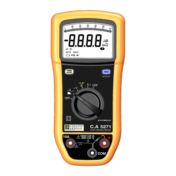
1. OVERVIEW The C.A 5271 is a stand-alone portable digital multimeter specially designed to combine all the functions for measurement of the following electrical quantities in a single instrument: AC voltage measurement with low input impedance (voltage measurements for electrical and electrical engineering... -
Page 5: The Keys
Volt Ampere Ω Symbol of the milli- prefix Symbol of the kilo- prefix Symbol of the mega- prefix Audible continuity measurement symbol Symbol for measurement and testing of semiconductor junctions Permanent mode Low-battery indicator 1.1.2 Measurement capacities exceeded (O.L) O.L (Over Load) is displayed when the measured signal exceeds the capacity of the instrument's scale There are two exceptions: •... -
Page 6: The Terminals
N° Function 1 and 6 OFF Mode - Multimeter shut down AC voltage measurement with low impedance (V LowZ AC, DC voltage measurement with high impedance (V) Resistance measurement (Ω) Audible continuity measurement Diode test AC, DC current measurement (A) 1.4. -
Page 7: Starting Up The Multimeter
2.2 Starting up the multimeter The switch is in the OFF position. Turn the switch to the function of your choice. All the display segments appear for a few seconds, then the screen for the selected function is displayed. The multimeter is now ready for measurements. Le commutateur est sur une autre position : appuyez sur la touche 2.3 Turning off the multimeter The multimeter can be turned off either manually by returning the switch to the OFF position, or automatically after ten... - Page 8 In V , the measurement signal goes through the low pass filter with a cut-off frequency of < 300 Hz. When LowZ measuring a voltage with a frequency in excess of 150 Hz, it is considerably reduced and therefore a significant error can occur.
- Page 9 3.1.4 Diode test To measure and check a semiconductor junction, proceed as follows: 1. Set the switch to 2. Press twice on . The symbol is displayed; 3. Connect the black lead to the COM terminal and the red lead to "+"; 4.
-
Page 10: Key Functions
3.2 Key functions The functions can be accessed by pressing a key repeatedly, using short or long presses. Every push on a key is validated by a sound signal. 3.2.1 When the quantity V or A is selected, the multimeter is in AUTO AC/DC. It then determines whether the measurement is an AC or DC measurement. -
Page 11: Specifications
4. SPECIFICATIONS 4.1 Reference conditions Influencing quantities: Reference conditions Temperature 23° C ± 5° C Relative humidity 45 % to 75 % Power supply voltage 9 V ± 1 V Frequency domain of the applied signal 40 Hz to 1 kHz Absence of electric field 4.2 Specifications of the reference conditions Uncertainties are given in:... - Page 12 4.2.2 AC Voltages LowZ The bandwidth is reduced to 300 Hz -3 dB. Specified Additional uncertainty Input Crest Range Resolution Uncertainty (±) measurement range F(Hz) typ. Impedance factor 3 at 600 mV 60 - 600 mV 0.1 mV 1.2 % R + 5 D 500 mV 45 <...
- Page 13 4.2.3 Resistance Special reference conditions: the input (+, COM) must not have been overloaded following the accidental application of voltage on the input terminals when the switch is on the Ω position. If this is the case, the return to normal can take about ten minutes.
- Page 14 4.2.7 DC Currents (10A DC) Specified Range measurement Resolution Voltage drop Protection Uncertainty (±) range 0,020 – 6,000 A 0.001 A 0.8 % R + 3 D Fast fuse 0.05 V / A 10 A (o 11 A) / 10 A / 20 A * 0,200 –...
-
Page 15: Operating Conditions
4.3 Operating conditions Operating conditions in use in storage Temperature -10° C to 50° C -20° C to 70° C Relative humidity (RH) 80 % RH at 50° C 90 % RH ( 45° C) ≤ ≤ 4.4 Construction specifications rigid case with yellow, elastomer thermo-adhesive over-moulding Screen LCD Display... -
Page 16: Variations In The Field Of Use
4.7 Variations in the operating range Influencing quantity Typical Range of Influence Influenced quantity influence < Battery voltage 7.5 V to 10 V 0.2 % R + 1 D 0.01 % R ± 0.2 D / 1° C V DC mV 0.02 % R ±... -
Page 17: Maintenance
Like all measuring or testing devices, the instrument must be checked regularly. This instrument should be checked at least once a year. For checking and calibration, contact one of our accredited metrology laboratories (information and contact details available on request), at our Chauvin Arnoux subsidiary or the branch in your country. -
Page 18: Warranty
An adaptation for a specific application not specified in the definition of the equipment or not indicated in the operating instructions; Damage due to shocks, falls or flooding. 7. TO ORDER The C.A 5271 The multimeter is delivered with: • Operating instructions on CD ROM in 5 languages •... - Page 19 3 F, 3 rd Building - N° 381 Xiang de Road - 200081 SHANGHAI Tel.: +86 21 65 21 51 96 - Fax: +86 21 65 21 61 07 USA - Chauvin Arnoux Inc - d.b.a AEMC Instruments 200 Foxborough Blvd. - Foxborough - MA 02035 Tel.: (508) 698-2115 - Fax: (508) 698-2118...
Need help?
Do you have a question about the C.A 5271 and is the answer not in the manual?
Questions and answers