Table of Contents
Advertisement
Quick Links
Advertisement
Table of Contents

Related Manuals for Chauvin Arnoux C.A 5273


Summary of Contents for Chauvin Arnoux C.A 5273
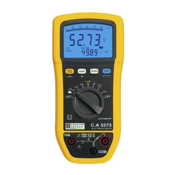
- Page 1 C.A 5273 TRMS MULTIMETER ENGLISH User’s manual...
- Page 2 E.g. Measurement on equipment installed upstream of the main fuse or building installation cut-off switch. You have just purchased a C.A 5273 multimeter and we thank you for your confidence in our products. To obtain the best service from your instrument: Read these instructions carefully;...
-
Page 3: Table Of Contents
CONTENTS 1. OVERVIEW .................................4 The display ............................4 1.2. The keys ..............................6 1.3. The switch..............................6 1.4. The terminals ............................7 2. Use ..................................7 First use ..............................7 Starting up the multimeter ........................7 Turning off the multimeter........................7 The stand...............................8 3. Functions................................8 Switch functions.............................8 Key functions ............................13 4. -
Page 4: Overview
1. OVERVIEW The C.A 5273 is a stand-alone portable digital multimeter specially designed to combine all the functions for measurement of the following electrical quantities in a single instrument: AC voltage measurement with low input impedance (voltage measurements for electrical and electrical engineering... - Page 5 1.1.1 The display symbols Symbols Description Measurement of the AC signal Measurement of the DC signal AUTO Auto-ranging HOLD Memorisation and display of memorised values Maximum RMS value Minimum RMS value .run r.un ru.n Capacitance meter, acquisition in progress ----- Frequency measurement impossible Measurement capacities exceeded Volt...
-
Page 6: The Keys
1.2. The keys The keyboard has 4 keys : MODE AC/DC, RANGE, MAX/MIN and HOLD. These are the keys: Figure 2: the keyboard keys N°. Function Selection of the display mode , ° C, ° F et du bar-graphe ( Selection of the measurement scale and activation/deactivation of the screen backlighting ( Activation of the MAX/MIN mode Memorisation of the values and display mode... -
Page 7: The Terminals
1.4. The terminals These are the multimeter terminals: Figure 4: the terminals N°. Input 6 A, 10 A current Common Other measurements 2. USE 2.1 First use Fit the battery shipped with the instrument as follows: 1. Using a screw driver, unscrew the four screws on the cover (item 1) located at the rear of the unit; 2. -
Page 8: The Stand
2.4 The stand There are two stand positions, one for suspending the multimeter (position 1) and the other providing a stand (position 2). To change the stand position, proceed as follows: Position 1: fit the stand studs into the upper holes located on Position 2: fit the stand studs into the lower holes located on the rear of the unit: the rear of the unit:... - Page 9 3.1.2 Voltage measurement The instrument measures the following types of voltages: DC voltage with high impedance (DC); AC voltage with high impedance (AC); AC voltage with low impedance (V LowZ In all cases "O.L " displays in excess of 1050 V and a beep sounds when the measurement exceeds 600 V. Volt : This position is designed for measurements on electrical installations.
- Page 10 3.1.4 Resistance measurement To measure the resistance, proceed as follows: 1. Set the switch to 2. Connect the black lead to the COM terminal and the red lead to "+"; 3. Place the test probes on the terminals of the component; Remark: all resistance measurements must be performed with the power off.
- Page 11 3.1.6 Diode test To measure and check a semiconductor junction, proceed as follows: 1. Set the switch to 2. Press twice on . The symbol is displayed; 3. Connect the black lead to the COM terminal and the red lead to "+"; 4.
- Page 12 3.1.8 Temperature measurement To measure the temperature, proceed as follows: 1. Set the switch to 2. Press to select the unit and scale of the temperature (° C or ° F). Remark: the default measurement unit displayed is ° C. 3.
-
Page 13: Key Functions
Detection of fuse tripping - or meltdown: If the fuse has melted, the circuit between COM and the 10 A socket is cut. The display shows zero. Set the switch to Ω. Connect the V socket to the 10 A socket (see above); leave the "COM" socket free. The display should show a result <... - Page 14 3.2.2 This key is used to manually select a measurement range or to activate the screen backlighting. The range defines the maximum range for measurements performed with the instrument. Remark: the Auto Range mode is activated by default. • In normal mode Type of press Resulting action short...
- Page 15 mode • Type of press Resulting action short exit from mode.
- Page 16 3.2.3 This key displays the MAX, MIN modes. Max and Min fill in the highest and lowest values of the measurement. • In normal mode Type of press Resulting action enters the MAX/MIN mode. Note that is displayed short in permanent operation. to select the quantities for MAX or MIN Reminder: the MAX quantity is displayed by default.
- Page 17 3.2.4 This key is used to memorise the measurements and quantities or to deactivate the automatic power-off function on the instrument. • In normal mode Type of press Resulting action memorises a measurement status at a given moment and then short makes it possible to view them successively on the display.
- Page 18 • mode Type of press Resulting action short freezes the display of each MAX, MIN quantity displayed. MAX, MIN,acquisition continues in the background. This is indicated by blinking of the MAX, MIN symbols. If you press a second time, you quit the mode .
-
Page 19: Specifications
4. SPECIFICATIONS 4.1 Reference conditions Influencing quantities: Reference conditions Temperature 23° C ± 5° C Relative humidity 45 % to 75 % Power supply voltage 9 V ± 1 V Frequency domain of the applied signal 40 Hz to 1 kHz Absence of electric field 4.2 Specifications of the reference conditions Uncertainties are given in:... - Page 20 4.2.2 AC voltages AC position LowZ The bandwidth is reduced to 300 Hz - 3 dB. In V , and there is no 60 mV scale. Frequency measurement is performed in LowZ the same way as the voltage measurement: with a bandwidth of 300 Hz Specified measurement Additional Input...
- Page 21 4.2.3 Frequency Special reference conditions : 150 mV < U < 600 V 0,15 A < I < 10 A When the switch is on the Hz or Volts position, the 300 Hz filter is not operational. When the switch is in the V position, the 300 Hz filter is activated for Volts and frequency LowZ Range...
- Page 22 4.2.7 Operation of the beep 4 kHz, 100 ms Beep indicating a valid key high sound 1 kHz, 100 ms Beep indicating an invalid key low sound Successive beeps for 30 seconds ending with a long beep 2 kHz 100 ms indicating that the instrument is being shut down medium sound 3 successive beeps with a space of 1 second in between (beep...
- Page 23 4.2.10 DC currents (10A DC) Specified measurement Voltage Range Resolution Uncertainty (±) Protection range drop 0.001 A 0.020 - 6.000 A 0.8 % R + 3 D Fast fuse 0.05 V / A 11 A/1000 V 0.01 A 0.200 - 20.00 A 0.8 % R + 2 D 10 A / 20 A Admissible overload: 10 A to 20 A for 30s max.
-
Page 24: Operating Conditions
4.3 Operating conditions Operating conditions in use in storage Temperature -10° C to 50° C -20° C to 70° C Relative humidity (RH) 80 % RH at 50° C 90 % RH ( 45° C) ≤ ≤ 4.4 Construction specifications rigid case with yellow, elastomer thermo-adhesive over-moulding LCD Display Screen... -
Page 25: Compliance With International Standards
4.6 Compliance with international standards Electrical safety Application of safety rules in compliance with standards NF EN 61010-1 + NF EN 61010-2-030 1000V, CAT III - 600V CAT IV, pollution level 2, double insulation. Electromagnetic compatibility Compliance with the NF EN 61326-1 and NF EN 61326-2-2 standards Emission: class B Immunity:... -
Page 26: Variations In The Field Of Use
4.7 Variations in the operating range Influencing quantity Typical Range of Influence Influenced quantity influence < Battery voltage 7.5 V to 10 V 0.2 % R + 1 D 0.01 % R ± 0.2 D / 1° C V DC mV 0.02 % R ±... -
Page 27: Maintenance
Like all measuring or testing devices, the instrument must be checked regularly. This instrument should be checked at least once a year. For checking and calibration, contact one of our accredited metrology laboratories (information and contact details available on request), at our Chauvin Arnoux subsidiary or the branch in your country. -
Page 28: Warranty
An adaptation for a specific application not specified in the definition of the equipment or not indicated in the operating instructions; Damage due to shocks, falls or flooding. 7. TO ORDER The C.A 5273 The multimeter is delivered with: • Operating instructions on CD ROM in 5 languages •... - Page 29 3 F, 3 rd Building - N° 381 Xiang de Road - 200081 SHANGHAI Tel.: +86 21 65 21 51 96 - Fax: +86 21 65 21 61 07 USA - Chauvin Arnoux Inc - d.b.a AEMC Instruments 200 Foxborough Blvd. - Foxborough - MA 02035 Tel.: (508) 698-2115 - Fax: (508) 698-2118...
Need help?
Do you have a question about the C.A 5273 and is the answer not in the manual?
Questions and answers