
Related Manuals for Interlogix TruVision 11 Series


Summary of Contents for Interlogix TruVision 11 Series
-
Page 1: Camera Installation
TruVision 11/31 Series Wi-Fi IP Camera Installation Guide P/N 1072907-EN • REV B • ISS 24APR15... - Page 2 Copyright © 2015 United Technologies Corporation, Interlogix is part of UTC Building & Industrial Systems, a unit of United Technologies Corporation. All rights reserved. Trademarks and patents Trade names used in this document may be trademarks or registered trademarks of the manufacturers or vendors of the respective products.
- Page 3 (1) This device may not cause harmful interference (2) This Device must accept any interference received, including interference that may cause undesired operation. Any changes or modifications not expressly approved by the party responsible for compliance could void the user’s authority to operate the equipment. Federal Communication Commission (FCC) Radiation Exposure Statement This equipment complies with FCC radiation exposure set forth for an uncontrolled environment.
- Page 4 Annex 3 B and A Wideband Data Transmission systems 2400.0-2483.5 MHz: Country Restriction Reasons/remarks Norway Implemented This subsection does not apply for the geographical area within a radius of 20 km from the centre of Ny-Ålesund. Italy Implemented The public use is subject to general authorization by the respective service provider.
- Page 5 (Cd), lead (Pb), or mercury (Hg). For proper recycling, return the battery to your supplier or to a designated collection point. For more information see: www.recyclethis.info. For contact information, see www.interlogix.com or Contact www.utcfssecurityproducts.eu. information...
-
Page 6: Table Of Contents
Content Introduction 7 Product overview 7 Installation 7 Installation environment 7 Package contents 8 Cable requirements 11 Camera description 11 Setting up the camera 12 Setting up Wi-Fi transmission 12 Accessing the SD card 19 Connecting a speaker 20 Mounting the wedge camera 21 Using the camera with a recorder Using the camera with TruVision Navigator 24 Ensuring corrosion resistance 24... -
Page 7: Introduction
Introduction Product overview This is the installation guide for TruVision 11-31 Series Wi-Fi IP camera models: TVW-1103 (1.3MPX Wi-Fi, 2.8mm lens, Grey, PAL) TVW-3103 (1.3MPX Wi-Fi, 2.8mm lens, Grey, NTSC) TVW-1104 (1.3MPX Wi-Fi, 2.8mm lens, White, PAL) TVW-3104 (1.3MPX Wi-Fi, 2.8mm lens, White, NTSC) ... -
Page 8: Package Contents
power supply to power the camera. Do not overload the power cord or adapter. Ventilation: Ensure that the location planned for the • installation of the camera is well ventilated. • Temperature: Do not operate the camera beyond the specified temperature, humidity or power source ratings. The operating temperature of the camera is between -30 to +60°C (-22 to 140°F). - Page 9 IP wedge camera Camera Installation manual CD with Configuration Manual and TruVision Device Finder Template A for mounting Screws with the converter pan Drywall anchor Φ7.5 x 24.5mm (3 pcs) Template B for mounting without the converter pan Screw M4 (4 x 25mm (3 pcs) Installation Guide...
- Page 10 Water joint: provide water 12 VDC connector: DC jack resistance to network socket to terminal connectors connection. with positive and negative indicators. Screws C: M4×8, 2pcs Tamper-resistant hex wrench Lens alignment tool Converter pan WEEE and battery disposal CAUTION: Use direct plug-in UL listed power supplies marked Class 2/CE certified or LPS (limited power source) of the required output rating as listed on the unit.
-
Page 11: Cable Requirements
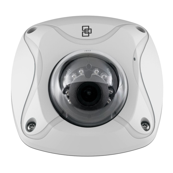
Cable requirements For proper operation, adhere to the following cable and power requirements for the cameras. Category 5 cabling or better is recommended. All network cabling must be installed according to applicable codes and regulations. Camera description Figure 1: IP wedge camera Camera cover/housing Alarm and Audio port Lens... -
Page 12: Setting Up The Camera
Setting up the camera Note: If the light source where the camera is installed experiences rapid, wide variations in lighting, the camera may not operate as intended. To quickly put the camera into operation: Prepare the mounting surface. Mount the camera using the appropriate fasteners. See “Mounting the wedge camera”... - Page 13 cause interference with your network. The result would lead to a reduction in transmission distance/range. Access the camera via a Wi-Fi network (Ad-Hoc mode) Note: The camera is in Ad-Hoc mode by default. The SSID is the serial number. Power up the camera. From your computer, search for the SSID that was set up for the camera for Ad-Hoc mode.
- Page 14 When connected, open TruVision Device Finder or Device Manager and change the IP address of the camera to that of the same subnet of the router. Note: The computer Wi-Fi IP address should also be in the same subnet. Installation Guide...
- Page 15 Log on the camera via web browser and browse to the Wi- Fi page. Select the desired Wi-Fi and enter the key, if required. Installation Guide...
- Page 16 Save Click to save the settings. When the camera is connected to the router, the ad-hoc is disconnected. On the laptop, select the Wi-Fi router and connect it. Open the device finder to check the WLAN IP address of the camera. Log in to the camera to see live view. Installation Guide...
- Page 17 Access the camera via a network cable When configuring the Wi-Fi settings for the first time, connect the camera to the router via a network cable and then open the web browser to complete the Wi-Fi setup by clicking Save. Installation Guide...
- Page 18 When the Wi-Fi Status changes from “Disconnected” to “Connected”, the Wi-Fi connection is set up successfully. The camera provides WPS (Wi-Fi Protected Setup) feature to easily set up a Wi-Fi connection to a Wi-Fi router. Installation Guide...
-
Page 19: Accessing The Sd Card
PBC mode: Push the WPS button on the Wi-Fi router. The WPS indicator will flash. (The WPS settings may be different per device. Please refer to the Wi-Fi router User Manual for details). Then check the checkbox and click the Connect button. -
Page 20: Connecting A Speaker
Connecting a speaker The camera has a built-in microphone to the collect audio input signal. For audio output, please connect an external speaker to the Audio Output and GND interface of the camera. The speaker is not supplied with the camera. Audio Output Note: The speaker need be powered correctly with a power supply. -
Page 21: Mounting The Wedge Camera
Mounting the wedge camera To mount the wedge camera on a wall or ceiling: Drill the holes for the mounting hardware in the mounting surface using the supplied drill template. To route the cables from the base of the camera, drill a cable access hole in the mounting surface. - Page 22 Mount the camera base to the converter pan or mounting surface, depending on the installation. Use the supplied lens alignment tool to adjust the pan [±30°], tilt [0 to 80°], and rotation direction [0 to 360°]. Installation Guide...
-
Page 23: Using The Camera With A Recorder
Adjusting tool Rotation Tilt Re-attach the dome cover to the camera. Using the camera with a recorder Please refer to the recorder user manuals for instructions on connecting and operating the camera with these systems. Installation Guide... -
Page 24: Using The Camera With Truvision Navigator
Using the camera with TruVision Navigator A camera must be connected to an Interlogix NVR or hybrid DVR in order to be operated by TruVision Navigator. Please refer to the TruVision Navigator user manual for instructions on operating the camera with the TruVision Navigator. -
Page 25: Specifications
The camera housing and hardware are designed and manufactured to ensure corrosion protection. However, it is necessary to seal the cable connection during the installation work. Following all local codes, use electrical tape or a corrosion-resistant conduit box to connect the cables as required. -
Page 26: Pin Definitions
Transmit output power 11b: 17±1.5 dBm @ 11Mbps 11g: 14±1.5 dBm @ 54Mbps 11n: 12.5±1.5 dBm Miscellaneous Connectors DC jack flying lead, RJ45 flying lead Operating temperature -30 to +60°C (-22°F to +140°F) Dimensions (L × W × H) 98 × 89 × 329 mm (3.86 ×3.49 ×... - Page 27 Figure 3: Cross-over cable White/Orange White/Orange Orange Orange White-Green White-Green Blue Blue White/Blue White/Blue Green Green White/Brown White/Brown Brown Brown Please make sure your connected cables have the same pin assignment and color as above before deploying the cables in your network.
- Page 28 Installation Guide...
Need help?
Do you have a question about the TruVision 11 Series and is the answer not in the manual?
Questions and answers