Table of Contents
Advertisement
Advertisement
Table of Contents

Related Manuals for Hills NVR-CH4

Summary of Contents for Hills NVR-CH4
- Page 1 Network Video Recorder NVR-CH4 NVR-CH8 NVR-CH16 Quick Guide V2.5...
-
Page 2: Table Of Contents
TABLE OF CONTENTS Overview ................................. 2 Front Panel ..............................2 Rear Panel ..............................8 Peripheral Connections ..........................10 Wiring of Alarm Input ..........................10 Wiring of Alarm Output ........................... 10 Using of Alarm Connectors ........................10 Accessing via Local Display........................... 11 Menu Structure ............................ -
Page 3: Overview
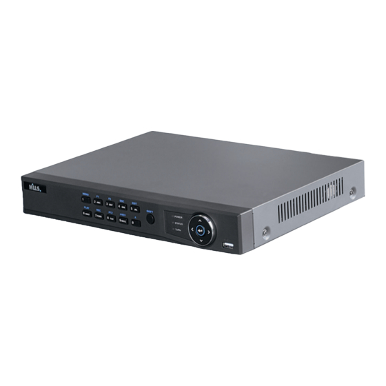
Overview Overview Front Panel NVR-4Channel (NVR-CH4) Name Description Power indicator turns yellow when system is running. Power Status indicator blinks red when data is being read from or written Status Status to HDD. Indicator Tx/Rx indictor blinks yellow when network connection is Tx/Rx functioning properly. - Page 4 The F2 button is used to change the tab pages. In PTZ control mode, it zooms in the image. Enter numeral “4”; Enter letters “GHI”; 4/GHI/ESC Exit and back to the previous menu. Enter numeral “5”; Enter letters “JKL”; 5/JKL/EDIT Delete characters before cursor;...
- Page 5 Name Function Description Tx/Rx Blinks green when network connection is functioning normally. In menu mode, the direction buttons are used to navigate between different fields and items and select setting parameters. In playback mode, the Up and Down buttons are used to speed up and slow down record playing, and the Left and Right buttons are DIRECTION used to move the recording 30s forwards or backwards.
- Page 6 Name Function Description Open the manual record interface. Enter numeral “8”; Enter letters “TUV”; 8/TUV/PTZ Access PTZ control interface. Enter numeral “9”; 9/WXYZ/PRE Enter letters “WXYZ”; Multi-channel display in live view. Enter numeral “0”; Shift the input methods in the editing text field. (Upper and lowercase, alphabet, symbols or numeric input).
- Page 7 Name Function Description In live view mode, these buttons can be used to switch channels. The Enter button is used to confirm selection in menu mode; or used to check checkbox fields and ON/OFF switch. In playback mode, it can be used to play or pause video. ENTER In single-frame play mode, pressing the Enter button will play the video by a single frame.
- Page 8 Name Function Description Shift the input methods in the editing text field. (Upper and lowercase, alphabet, symbols or numeric input). Double press the button to switch the main and auxiliary output. Move the active selection in a menu. It will move the selection up and down.
-
Page 9: Rear Panel
Rear Panel NVR-4Channel (NVR-CH4) NVR-8Channel (NVR-CH8) Item Description Power Supply 48V DC power supply for NVR-CH4 and AC 100~240V for NVR-CH8. Audio In RCA connector for audio input. HDMI Interface HDMI video output connector. LAN Network Interface 1 10 /100 /1000 Mbps self-adaptive Ethernet interface Audio Out RCA connector for audio output. - Page 10 NVR-16Channel (NVR-CH16) Item Description LAN Interface 1 network interface AUDIO OUT RCA connector for audio output. LINE IN RCA connector for audio input. HDMI HDMI video output connector. USB 3.0 interface Universal Serial Bus (USB) ports for additional devices such as USB mouse and USB Hard Disk Drive (HDD).
-
Page 11: Peripheral Connections
Peripheral Connections Wiring of Alarm Input The alarm input is an open/closed relay. To connect the alarm input to the device, use the following diagram. Note: If the alarm input is not an open/close relay, please connect an external relay between the alarm input and the device. -
Page 12: Accessing Via Local Display
Accessing via Local Display Menu Structure The menu structure NVR-4CH and NVR-8CH: Menu Playback Maintenance Shutdown Export Manual Record Camera Configuration Normal Record General Schedule Camera General System Info Logout Event Alarm Advanced Parameters Network Shutdown Information Advanced Image Alarm Reboot Import/Export Holiday... -
Page 13: Startup And Shutdown
Startup and Shutdown Proper startup and shutdown procedures are crucial to extend the life of the NVR. To start your NVR: Steps: 1. Check the power supply is plugged into an electrical outlet. It is HIGHLY recommended that an Uninterruptible Power Supply (UPS) be used in conjunction with the device. The Power button on the front panel should be red, indicating that the device has power. - Page 14 Steps: 1. Right-click the mouse when you in the live view mode to show the right-click menu. 2. Select Camera in the pop-up menu to enter the Camera Management interface. The online cameras with same network segment will be displayed in the camera list. Click the button to add the camera.
-
Page 15: Recording
Icon Explanation Icon Explanation The camera is disconnected; you can The camera is connected. click the icon to get the exception information of camera. Delete the IP camera Advanced settings of the camera. To add other IP cameras: Click the Custom Adding button to pop up the Add IP Camera (Custom) interface. You can edit the IP address, protocol, management port, and other information of the IP camera to be added. -
Page 16: All-Day Recording
All-day Recording Steps: 1. On the live view window, right lick the window and move the cursor to the Start Recording option, and select Continuous Record or Motion Detection Record on your demand. 2. And click the Yes button in the popup Attention message box to confirm the settings. Then all the channels will start to record in the selected mode. - Page 17 Option 2: Steps: 1. Enter the Playback menu. Mouse: right click a channel in live view mode and select Playback from the menu. Under multi-screen live view, record files of the selected channel will be played back. Note: Pressing numerical buttons will switch playback to related channels during playback process. 2.
-
Page 18: Backup
Just check the channel or channels if you want to switch playback to another channel or execute simultaneous playback of multiple channels. Backup Recorded files can be backed up to various devices, such as USB flash drives, USB HDDs or a DVD writer. Steps: 1. - Page 19 3. Select backup device and click Export button to start exporting. 4. Check backup result. Choose the recording file in Export interface and click button to check it.
-
Page 21: Accessing Via Web Browser
Accessing via Web Browser Accessing via Web Browser Logging In You can get access to the device via web browser. Open a web browser, input the IP address of the device and then press Enter. The login interface appears: Input the user name and password, and click the Login button. Note: ... - Page 22 Interface Introduction Name Description Displays the list of channels and the playing and recording status of each channel. Channel List Note: The stream type can be switched by clicking the icon before the channel name: stands for main stream and for sub-stream.
-
Page 23: Recording
Start/Stop all recording Enable/Disable digital zoom Previous/Next page Full screen Recording Two recording types can be configured: Manual and Scheduled. The following section introduces the configuration of scheduled recording. Steps: 1. Click Remote Configuration> Camera Settings> Record Schedule to enter Record Schedule settings interface. -
Page 24: Playback
Configure All Day or Customize Record: If you want to configure the all-day recording, please check the All Day checkbox. If you want to record in different time sections, check the Customize checkbox. Set the Start Time and End Time. Note: Up to 8 segments can be configured and each segment cannot be overlapped. -
Page 25: Log
Button Description Button Description Play/Pause Stop Slow down Speed up Play by single frame Capture Stop all playback Download Video clip Open/Close audio Full screen Reverse playback 6. You can drag the progress bar with the mouse to locate the exact playback point. You can also input the time in the textbox and click button to locate the playback point. -
Page 27: Specifications
Specifications Model NVR-CH4 NVR-CH8 NVR-CH16 Part no S47094 S47095 S47096 IP video input 4-ch 8-ch 16-ch Video/Audio 1-ch, RCA (2.0 Vp-p, 1kΩ) Two-way audio input input Incoming 25Mbps 50Mbps 100Mbps bandwidth Outgoing 80Mbps Network bandwidth Remote connection Recording 5MP/3MP/1080P/UXGA/720P/VGA/4CIF/DCIF/2CIF/CIF/QCIF resolution... -
Page 28: Hdd Storage Calculation Chart
4 independent 100 8 independent 100 independent Interface network network 100 PoE network interface interface interface Max. Power 120W 200W Supported AF and AT standard 48V DC 220V AC 100-240V AC Power supply ≤ 10W ≤ 20W Consumption (without hard disk) Working -10 ºC ~ +55 ºC (+14 ºF~ + 131 ºF) temperature... - Page 29 Note: Supplied values for storage space used are just for reference. The storage values in the chart are estimated by formulas and may have some deviation from actual value.
- Page 30 For further information, including full user and installation manual, and technical support please visit: www.hills.com.au/videosecurity...
Need help?
Do you have a question about the NVR-CH4 and is the answer not in the manual?
Questions and answers
Reset password
The provided context does not include a clear password reset procedure for the Hills NVR-CH4. However, it mentions that the default admin password is 'admin'. If the password has been changed and forgotten, the context does not provide a reset method. You may need to contact Hills technical support for further assistance.
This answer is automatically generated