Table of Contents
Advertisement
Quick Links
INSTALLER: Leave this manual with party responsible for use and operation.
OWNER: Retain this manual for future reference.
This fireplace uses SL1100 Series Chimney
2" CLEARANCE TO COMBUSTIBLES AND BUILDING INSULATION FROM CHIMNEY REQUIRED.
NOTICE: DO NOT discard this manual!
Model(s):
WOODBURNING FIREPLACE
Installation and service of this fireplace should be
performed by qualified personnel. Vermont Cast-
ings Group recommends NFI certified profession-
als, or technicians supervised by an
NFI certified professional.
VCG Designer Series • DSR42 Installation Manual • 4012-134 • Rev A • 02/20/15
Installation Manual
Installation and Fireplace Setup
WARNING: If the information in these
instructions is not followed exactly, a fire
or explosion may result causing property
damage, personal injury, or death.
• DO NOT store or use gasoline or other flam-
mable vapors and liquids in the vicinity of this
or any other appliance.
• DO NOT overfire. Overfiring will void your
warranty.
• Comply with all minimum clearances to com-
bustibles as specified. Failure to comply may
cause house fire.
WARNING
HOT SURFACES!
Glass and other surfaces are hot during
operation AND cool down.
Hot glass will cause burns.
• DO NOT touch glass until it is cooled
• NEVER allow children to touch glass
• Keep children away
• CAREFULLY SUPERVISE children in same room as
fireplace.
• Alert children and adults to hazards of high temperatures.
High temperatures may ignite clothing or other flammable
materials.
• Keep clothing, furniture, draperies and other flammable
materials away.
WARNING
Fire Risk.
For use with solid wood fuel only.
Other fuels may overfire and generate
poisonous gases (i.e. carbon monoxide).
1
Advertisement
Table of Contents

Related Manuals for Vermont Castings DSR42


Summary of Contents for Vermont Castings DSR42
-
Page 1: Woodburning Fireplace
For use with solid wood fuel only. als, or technicians supervised by an NFI certified professional. Other fuels may overfire and generate poisonous gases (i.e. carbon monoxide). VCG Designer Series • DSR42 Installation Manual • 4012-134 • Rev A • 02/20/15... -
Page 2: Table Of Contents
D. Mantel and Wall Projections C. Termination Requirements E. Sidewalls/Surrounds 8 Fireplace Setup A. Gas Log/Lighter Provision 9 Reference Materials A. Chimney Components B. Optional Components VCG Designer Series • DSR42 Installation Manual • 4012-134 • Rev A • 02/20/15... - Page 3 Comments: Further description of the issues, who is responsible (Installer/Builder/Other Trades, etc.) and corrective action needed: Comments communicated to party responsible __________________________ by ______________________on _________ (Builder/Gen. Contractor) (Installer) (Date) 4012-136 • Rev A • 02/20/15 VCG Designer Series • DSR42 Installation Manual • 4012-134 • Rev A • 02/20/15...
-
Page 4: Product Specific & Important Safety Information
Improper installation, adjustment, alteration, service or maintenance can cause injury or property damage. For assistance or additional information, consult a qualified installer, service agency or your dealer. VCG Designer Series • DSR42 Installation Manual • 4012-134 • Rev A • 02/20/15... -
Page 5: Getting Started
4 ft. Decorative facing (1.322 m) off and trim ground level. Hearth extension Outside combustion air Factory-built fireplace Protective metal hearth strip(s) Figure 2.1 Typical Fireplace System VCG Designer Series • DSR42 Installation Manual • 4012-134 • Rev A • 02/20/15... -
Page 6: Design And Installation Considerations
20 in. (508 mm) 1/2 in. (13 mm) all configurations 12 in. (305 mm) min. to perpendicular 64 in. wall. (1626 mm) Figure 2.2 Fireplace Locations VCG Designer Series • DSR42 Installation Manual • 4012-134 • Rev A • 02/20/15... -
Page 7: Locating Fireplace & Chimney
• Below adjacent structure • Insulated exterior chase • Lower roof line in cooler climates • Avoid outside wall Windward Leeward Figure 2.3 Recommended Chimney Locations Multi-level Roofs VCG Designer Series • DSR42 Installation Manual • 4012-134 • Rev A • 02/20/15... -
Page 8: Tools And Supplies Needed
Report to your dealer any parts damaged in shipment. • Read all the instructions before starting the installation. Follow these instructions carefully during the installation to ensure maximum safety and benefit. VCG Designer Series • DSR42 Installation Manual • 4012-134 • Rev A • 02/20/15... -
Page 9: Framing And Clearances
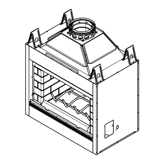
14 in. 7-1/2 in. 5-7/8 in. 14 in. (1067 mm) (356 mm) (192 mm) (149 mm) (356 mm) 8-5/8 in. (219 mm) Figure 3.1 Fireplace Dimensions VCG Designer Series • DSR42 Installation Manual • 4012-134 • Rev A • 02/20/15... -
Page 10: Clearances
Canada. 1/2 in. (13 mm) to sides of appliance 48 in. 1219 mm 0 in. to floor Figure 3.2 Clearances to Combustible Materials VCG Designer Series • DSR42 Installation Manual • 4012-134 • Rev A • 02/20/15... -
Page 11: Construct The Chase
Figure 3.3. This will help reduce heat loss from the home around the fireplace. Figure 3.4 Chase Constructions VCG Designer Series • DSR42 Installation Manual • 4012-134 • Rev A • 02/20/15... -
Page 12: Frame The Fireplace
The fireplace should be positioned so the face of the non- combustible material on the fireplace will be flush with the face of the drywall on the walls. Level the fireplace and shim as necessary. VCG Designer Series • DSR42 Installation Manual • 4012-134 • Rev A • 02/20/15... -
Page 13: Protective Metal Hearth Strips
Raised Platform 2 in. 1 in. (25 mm) min. (51 mm) overlap Floor 2 in. (51 mm) Figure 3.7 Protect the Front of an Elevated Platform VCG Designer Series • DSR42 Installation Manual • 4012-134 • Rev A • 02/20/15... -
Page 14: Outside Air Kit
• Secure flex duct with screws or wire ties. Figure 3.9 Outside Air Installation VCG Designer Series • DSR42 Installation Manual • 4012-134 • Rev A • 02/20/15... -
Page 15: Chimney And Termination Requirements
& g Ceiling Firestop 11-10 in. (279-254 mm) adapter required in 58-7/8 in. Canada. (1495 mm) a,b,c,f Effective Height Figure 4.1 Chimney Requirements VCG Designer Series • DSR42 Installation Manual • 4012-134 • Rev A • 02/20/15... -
Page 16: Offsets/Returns
Proper assembly of air cooled chimney parts results in an overlap of chimney joints of 1-1/4 in. (32 mm). Effective length is built into this table. VCG Designer Series • DSR42 Installation Manual • 4012-134 • Rev A • 02/20/15... -
Page 17: Termination Requirements
In a staggered installation with both gas and wood terminations, the wood termination cap must be higher than the gas termination cap. Figure 4.3 Multiple Chimney Locations VCG Designer Series • DSR42 Installation Manual • 4012-134 • Rev A • 02/20/15... -
Page 18: Chimney Installation
Attic shield movement Ceiling firestops are required where chimney passes through ceiling or floor Figure 5.1 Typical Chimney System - Guidelines for Chimney System Installation VCG Designer Series • DSR42 Installation Manual • 4012-134 • Rev A • 02/20/15... -
Page 19: Assemble Chimney Sections
Vertical straight runs of chimney must be supported every 35 ft (10.7 m). Figure 5.2 Assembling Chimney Sections WARNING! Risk of Fire! DO NOT install substitute or damaged chimney components. VCG Designer Series • DSR42 Installation Manual • 4012-134 • Rev A • 02/20/15... -
Page 20: Secure Offset/Return
• Use an attic insulation shield if the ceiling is insulated. The ceiling firestop may then be attached above or below the joists. VCG Designer Series • DSR42 Installation Manual • 4012-134 • Rev A • 02/20/15... -
Page 21: Install Attic Insulation Shield
If they have been connected correct- Ceiling Firestop Pipe (330 mm) ly, they will not disengage when tested. Figure 5.7 Install Attic Insulation Shield (firestop below ceiling) VCG Designer Series • DSR42 Installation Manual • 4012-134 • Rev A • 02/20/15... -
Page 22: Roof Penetration
WARNING! Risk of Fire! DO NOT caulk the pipe to the chase top collar. • Caulk all seams to prevent leaks. .018 (26 ga) min. Galvanized Chase Top Figure 5.9 Chase Top Construction VCG Designer Series • DSR42 Installation Manual • 4012-134 • Rev A • 02/20/15... -
Page 23: Termination Cap Requirements
1-1/2 in. (38 mm). Figure 5.12 Installing an ST1175/ST475 Square Termination Cap Figure 5.10 Installing a TR11/TR444 Round Termination Cap VCG Designer Series • DSR42 Installation Manual • 4012-134 • Rev A • 02/20/15... - Page 24 Figure 5.13 Installing a TCT1175 Terra Cotta Cap Termination cap pipe and chimney section must overlap 1-1/2 in. (38 mm) Figure 5.14 Installing a DTO134/DTO146/DTS134/DTS146 Cap VCG Designer Series • DSR42 Installation Manual • 4012-134 • Rev A • 02/20/15...
-
Page 25: Shrouds
3 in (76 mm) air space from bottom of shroud Chase Top to top of chase. Figure 6.3 Shroud & TR Series cap with no Radiation Shield VCG Designer Series • DSR42 Installation Manual • 4012-134 • Rev A • 02/20/15... -
Page 26: Mailbox Style Shroud
Shield Height Base Dimension Min. Height Above Bottom of Termination Cap Min. Opening Width Min. Opening Width Min. Opening Height Figure 6.5 Roofed Style Shroud Dimensions VCG Designer Series • DSR42 Installation Manual • 4012-134 • Rev A • 02/20/15... -
Page 27: Finishing
2 in. (51 mm) Figure 7.2 Decorative Facing VCG Designer Series • DSR42 Installation Manual • 4012-134 • Rev A • 02/20/15... -
Page 28: Hearth Extension, Building And Finishing
0.46 2.18 1/2 in. discoloration, cracking or other material failures of finishing materials due to heat exposure or smoke. 14.3-20.0 0.07-0.05 14 5/8 in. - 20 3/8 in. Marble • Choose finishing materials carefully. CAT. # 1676 Figure 7.3 Hearth Extension Dimensions VCG Designer Series • DSR42 Installation Manual • 4012-134 • Rev A • 02/20/15... -
Page 29: Fireplace Installed Flush On The Floor And Hearth Extension Raised To Bottom Of Firebox Opening
Framing Material equivalent Figure 7.4 Hearth Extension Construction Figure 7.6 Raised Platform Hearth Extension-Framing Non-combustible Finishing Materials Figure 7.7 Raised Platform Hearth Extension-Finishing VCG Designer Series • DSR42 Installation Manual • 4012-134 • Rev A • 02/20/15... -
Page 30: Raised Hearth Extension And Raised Fireplace
Protective Metal Hearth Strips Non-combustible Floor and platform constructed of Framing Material wood or other combustible material Figure 7.8 Raised Hearth Extension and Fireplace Framing Materials VCG Designer Series • DSR42 Installation Manual • 4012-134 • Rev A • 02/20/15... -
Page 31: Non-Combustible Sealant Material
Figure 7.9 Place Non-combustible Sealant WARNING! Risk of Fire! Vermont Castings Group is not responsible for discoloration, cracking or other material failures of finishing materials due to heat exposure or smoke. • Choose finishing materials carefully. VCG Designer Series • DSR42 Installation Manual • 4012-134 • Rev A • 02/20/15... -
Page 32: Mantel And Wall Projections
Steel, iron, maximum brick, tile, concrete, slate, tile, plasters Measured from top of fireplace opening Seal joint with non-combustible sealant Figure 7.10 Mantel Specifications VCG Designer Series • DSR42 Installation Manual • 4012-134 • Rev A • 02/20/15... -
Page 33: Sidewalls/Surrounds
[1194 mm] width of fireplace 12 in. 12 in. [305 mm] [305 mm] Figure 7.11 Mantel Leg, Surround or Wall Projection (acceptable on both sides of opening) VCG Designer Series • DSR42 Installation Manual • 4012-134 • Rev A • 02/20/15... -
Page 34: Fireplace Setup
National Fuel Gas Code Z223.1, Latest edition. WARNING! Do Not operate an unvented gas log set in this fireplace with the chimney removed. VCG Designer Series • DSR42 Installation Manual • 4012-134 • Rev A • 02/20/15... -
Page 35: Reference Materials
SL4 - 10 in. (254 mm) CT-Series SL11 - 11 in. (279 mm) 20-3/4 in. DT-Series (527 mm) Outside Diameter 13 in. (330 mm) SL11/SL4 Chimney Stabilizer VCG Designer Series • DSR42 Installation Manual • 4012-134 • Rev A • 02/20/15... - Page 36 39-7/8 in. (711 mm) (1013 mm) RF571 Roof Flashing 13 in. (330 mm) CB576 Chimney Joint Band 15-3/4 in. (400 mm) TR11/TR444 - Round Termination Cap CT-11A VCG Designer Series • DSR42 Installation Manual • 4012-134 • Rev A • 02/20/15...
- Page 37 ST1175/ST475 - Square Termination Cap 20 in. (508 mm) 17 in. (432 mm) 9-3/8 in. (238 mm) 10-1/4 in. (260 mm) TCT1175 - Terra Cotta Cap VCG Designer Series • DSR42 Installation Manual • 4012-134 • Rev A • 02/20/15...
- Page 38 22 3/4 in. 21 3/16 in. (577 mm) (538 mm) 46 in. 46 in. (1168 mm) (1168 mm) 26 in. 26 in. (660 mm) (660 mm) DTS146 DTO146 VCG Designer Series • DSR42 Installation Manual • 4012-134 • Rev A • 02/20/15...
-
Page 39: Optional Components
HX4 Hearth Extension 1/2 in. (13 mm) LDS-BV Decorative Shroud Catalog # 12.5 15.5 LDS-BV DM1242 Bi-fold doors with black trim DM1242S Bi-fold doors with stainless steel trim VCG Designer Series • DSR42 Installation Manual • 4012-134 • Rev A • 02/20/15... - Page 40 Vermont Castings Group 149 Cleveland Drive Paris, Kentucky 40361 www.vermontcastingsgroup.com VCG Designer Series • DSR42 Installation Manual • 4012-134 • Rev A • 02/20/15...
Need help?
Do you have a question about the DSR42 and is the answer not in the manual?
Questions and answers