
Subscribe to Our Youtube Channel
Related Manuals for PowerMaster CSWC


Summary of Contents for PowerMaster CSWC
- Page 1 PowerMaster Installation Manual SWING GATE OPERATOR UL 325 AND UL 991 LISTED...
-
Page 2: Table Of Contents
TABLE OF CONTENTS MODEL “CSWC” & ”CSWI” COMMERCIAL & /INDUSTRIAL SWING GATE OPERATOR I M P O R T A N T ! Important Safety Information……………..……………..3 UL Installation and Safety Considerations……..…..… …… System Designer Safety Instructions……...…….……..6 Installer Safety Instructions ………...……..………….....8 FOR SWING GATE OPERATING SYSTEMS End User Safety Warnings …….……………………... -
Page 3: Ul Installation And Safety Considerations
U/L INSTALLATION AND SAFETY CLASS III- INDUSTRIAL/LIMITED ACCESS VEHICULAR GATE OPERATOR CONSIDERATIONS A vehicular gate operator (or system) intended for use in an INSTALLATION CLASSES industrial location or building such as a factory or loading dock area or other locations not intended to service the general CLASS I –... -
Page 4: System Designer Safety Instructions
SYSTEM DESIGNER SAFETY INSTRUCTIONS The illustrations and descriptive captions found on the following pages provide precautions to help eliminate ▲ 1. Familiarize yourself with the precautions and injuries or fatalities. Familiarize yourself with them when warnings for the installer. Users are relying on your designing the total system. -
Page 5: Installer Safety Instructions
INSTALLER SAFETY INSTRUCTIONS ▲ 7. You must install a pushbutton control or key switch to allow for normal operation of the gate if the BEFORE INSTALLATION automatic controls do not work. Locate the push button or key switch and small warning placard ▲... - Page 6 ▲ 6. Attach large warning signs provided to each side of the gate or fence in the most conspicuous place. DURING INSTALLATION Mount control station and smaller warning placard together within sight of the gate opening. ▲ 1. Be aware of all moving parts and avoid close proximity to any pinch points.
-
Page 7: End User Safety Warnings
END-USER SAFETY WARNINGS ▲ DO NOT allow children to play near your gate, or to operate the gate. The manufacturer of the gate operator does not know what type of gate you have, or what type of automatic system is installed on your gate. -
Page 8: Before Installing Operator
▲ 8. If your gate closes automatically, loop detectors INSTALLATION INSTRUCTIONS should be installed to detect the presence of a ▲ WARNING: DO NOT APPLY POWER UNTIL vehicle. TOLD TO DO SO! RISK OF ELECTRICAL SHOCK OR INJURY MAY RESULT! ▲... -
Page 9: Left Hand/Right Hand Conversion
CEMENT PAD LAYOUT: 1. Lay out per drawing below depending on if you have a CSWC or a CSWI. PUBLIC AREA 2. Locate electrical conduit and mounting bolts. OR STREET Note: Bolt pattern must be parallel to fence line as shown. -
Page 10: Operator Installation
CSWI PAD LAYOUT OPERATOR INSTALLATION 1. Mount operator on cement pad, locating electrical conduit under access hole, and secure position with CEMENT PAD 22" 1/2 inch hardware. ELECTRICAL 10" 10" CONDUIT 36" 2. Set control arm on output shaft of operator without drive key, and install control arm extension using 10-1/4"... - Page 11 5. Locate gate bracket in position on gate, as shown 7. Move control arm to its open position. below, and clamp in position. Note: Open position of gate may be adjusted slightly with limit switch adjustment, but when finished, open 6.
- Page 12 MANUAL OPERATION Disconnect operator control linkage in order to manually operate the gate as follows: ELECTRICAL SET-UP AND CONNECTIONS 1. Unscrew and remove (2) hand knob bolts connecting CONNECTION OF INCOMING POWER control arm extension to control arm. WARNING: DO NOT APPLY POWER UNTIL TOLD TO 2.
- Page 13 length of wire runs should be figured at half that shown on INSTALLATION OPTIONS the chart. This unit must be grounded in accordance with N.E.C. and local codes. LEFT/RIGHT HAND CONVERSION: Determine the hand of the operator required for this installation by checking the direction the gate moves in order to open, when viewed from inside the fence.
- Page 14 NOTE: This unit is factory setup for RIGHT HAND CONNECTION OF A THREE-BUTTON STATION: operation. To convert operator to left hand operation move dipswitch #2 to on position. NOTE: All control contacts must be NORMALLY OPEN unless dipswitch #3 is placed to the “ON” position, which will change the circuitry to accept a NORMALLY CLOSED STOP BUTTON.
-
Page 15: Master/Slave Installation
1. Connect a wire from the common connection of the MASTER/SLAVE INSTALLATION control station to any “COM” terminal on the control board. NOTE: A single unit is considered a Master. In a Master/Slave installation, one unit must be converted to 2. - Page 16 5. Connect a third wire from any “COM” terminal on the LIMIT ADJUSTMENT PROCEDURE Master operators control board, to any “COM” ▲ WARNING: READ ENTIRE PROCEDURE BEFORE terminal on the Slave operators control board. STARTING. TURN OFF MAIN POWER BEFORE MAKING ANY ADJUSTMENTS! MASTER OPERATOR SLAVE OPERATOR...
-
Page 17: Limit Adjustment
CLOSE LIMIT SWITCH ADJUSTMENT: EMERGENCY CONTROL STATION OPTION 1. Press close button on control station, gate should stop Provision has been made to change the control station before full close position is reached. If gate does not stop operational mode to one that would only be activated when when close position is reached, PRESS STOP BUTTON! the entrapment sensing system is in stop mode;... -
Page 18: Timer To Close
TIMER TO CLOSE OPTION AUDIBLE PRE - MOVE WARNING The operator is equipped with a timer to close option for use By moving Dipswitch #4 to the “ON” position the option of a with OPEN ONLY control devices such as a radio control, or 3 second Audible Warning, before gate movement, may be card key control. -
Page 19: Auxiliary Circuit
AUXILIARY CIRCUIT FOR USE WITH GATE LOCKS, OPTION #2 – POWER SUPPLIED DURING GATE MOVEMENT WARNING LIGHTS, ETC The following diagram shows the connection of a An auxiliary 24 VAC power circuit, for use with a 24V device, such as a solenoid operated gate lock, control relay, has been provided. -
Page 20: Accessory Connections
ACCESSORY CONNECTIONS LOOP DETECTOR SYSTEMS AND INSTALLATION The diagram below depicts the typical loop options for a Slide Gate installation. RADIO CONTROL INSTALLATION 1. The Exit Loop provides a signal to open the gate A Three or Four wire radio control receiver can be when a vehicle enters the loop zone. - Page 21 LOOP INSTALLATION 2. Cut the required groove as shown in the diagram below at the locations laid out in Step #1. 1. Layout the desired loop locations per the diagram. The standard size chart below will give an approximate length of Loop Wire wire required for various loop dimensions and number of (See Chart)
-
Page 22: Safety Device Connections
6. Fill over the loop wires in the groove with a SHADOW LOOP CONNECTION recommended loop sealant. Contact your distributor LD17 for available sealants. OPEN PHOTO LD13 CLOSE PHOTO FORCE 7. Mount the loop detector in the operator and connect ADJUSTMENT the wire loop. -
Page 23: Clutch Adjustment
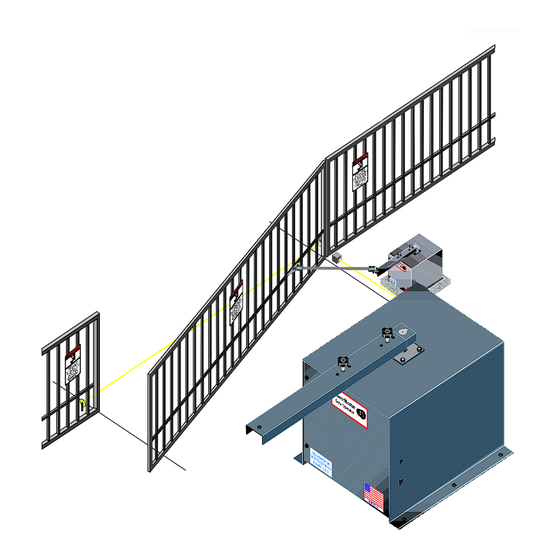
For heavy gates increase the force setting until it is just over CLUTCH ADJUSTMENT what is required to move the gate smoothly without any nuisance tripping. NOTE: The clutch comes pre-adjusted from the factory and will function properly for the majority of NOTE: Most required... - Page 24 8. Loosen locking set screw in adjustment nut. 1. Install electric edge sensors in locations shown below. 9. Tighten adjustment nut clockwise ¼ of a turn. NOTE: A separate pedestrian gate must be installed if 10. Turn on power and run gate to check the adjustment. there is no other entry access but the vehicular gate.
- Page 25 NOTE: The outside edge and vertical edge are connected 2. Photocells should be installed across the gate to “CLO EDG” and “COM” terminals. opening and behind the gate (as shown below) at least 10 inches above ground. 3. After sensors are mounted and electrically connected, NOTE: A separate pedestrian gate must be turn on the power.
- Page 26 NOTE: Close photocell is connected to “CLO PHO” and “COM” terminal. Open photocell is connected to “OPN PHO” and “COM” terminal. LED & DIPSWITCH INFORMATION FOR 2004 UMCB-01 CONTROL BOARD AFTER SENSORS ARE CONNECTED: 1. Turn on power. 2. Make sure the photo-beams are properly aligned per the manufacturer’s specifications.
- Page 27 MAINTENANCE SUGGESTIONS The Reducer is completely sealed and should not require lubrication. Periodically check drive belt and all hardware (nuts, bolts, screws, etc) for tightness. Maintenance Log/Notes ______________________________________________ ______________________________________________ ______________________________________________ ______________________________________________ ______________________________________________ ______________________________________________ ______________________________________________ ______________________________________________ ______________________________________________ ______________________________________________ ______________________________________________ ______________________________________________ ______________________________________________ ______________________________________________ ______________________________________________ ______________________________________________...
- Page 28 Limited 5 Year Warranty ______________________________________________ ______________________________________________ PowerMaster warrants all gate operators to be free of defects in materials and workmanship for a period of Five (5) years from date ______________________________________________ of purchase. If any part is found to be defective during this period, ______________________________________________ new parts will be furnished free of charge.
- Page 29 Model CSWC/CSWI Location Installed: Date Installed____________ Address _______________ Serial # ________________ Address _______________ Address _______________ Installer’s Information Company Name _____________________________ Company Address ___________________________ Company Address ___________________________ Company Address ___________________________ Company Telephone # ________________________ Company Contact ____________________________...
Need help?
Do you have a question about the CSWC and is the answer not in the manual?
Questions and answers