Table of Contents
Advertisement
Quick Links
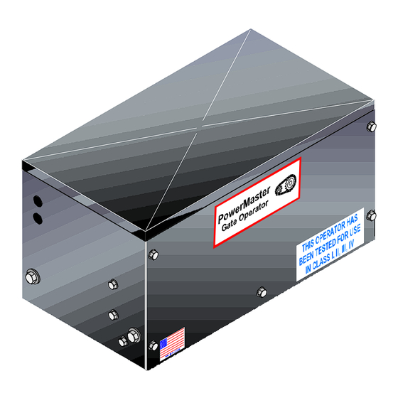
PowerMaster
Installation Manual
RESIDENTIAL SLIDE GATE OPERATOR
UL 325 AND UL 991 LISTED
MODEL "RSG"
RESIDENTIAL SLIDE GATE OPERATOR
Installation & Setup Procedure
Accessory Connections
U L
R
TABLE OF CONTENTS
Important Safety Information.......................................3
UL Installation and Safety Considerations.....................4-5
System Designer Safety Instructions................................6
Installer Safety Instructions ........................................ 7-10
End User Safety Warnings ..................................11-14
Manual Operation...................................................15
Safety Warnings...............................................16-17
Before Installing Operator........
Installation of Cement Pad.........................................19
...................................
Installation of Operator
Electrical Connections ...................
Limit Adjustment ..............................................26-28
Master/Slave Installation .........................................29
Timer To Close............................
Connection of a 3 Button........................
Connection of a Radio.............................................32
Loop Detector Systems............................................33
Loop Installation (Standard Layout Chart)......................34
Cutting The Required Groove............................................35
Loop Connections.............................................................36
Inherent Obstruction Sensing Device...................................37
Contact - Sensing Edge ...................
Non-Contact - Photo Eyes ................
Maintenance Log/Notes..............................................42
Warranty............................................................43
2
.........
.....
........
....... ... 18
..19-23
....... ...... ... ...
24-25
......
..................30
....
.............31
...
.
.
38-39
...
40-41
Advertisement
Table of Contents

Related Manuals for PowerMaster RSG


Summary of Contents for PowerMaster RSG
-
Page 1: Table Of Contents
TABLE OF CONTENTS MODEL “RSG” RESIDENTIAL SLIDE GATE OPERATOR Important Safety Information……………..……………..3 UL Installation and Safety Considerations……..…..……4-5 PowerMaster System Designer Safety Instructions……...…….……..6 Installer Safety Instructions ………...……..…………..7-10 End User Safety Warnings …….………………………11-14 Manual Operation………………….…..……...….……..15 Safety Warnings………………………………………..16-17 Installation & Setup Procedure …...…... -
Page 2: Ul Installation And Safety Considerations
U/L INSTALLATION AND SAFETY I M P O R T A N T ! CONSIDERATIONS FOR SLIDE GATE OPERATING SYSTEMS INSTALLATION CLASSES SAFETY IS EVERYONE’S BUSINESS CLASS I – RESIDENTIALVEHICULAR GATE OPERATOR Automatic gate operators provide convenience and security to users. -
Page 3: System Designer Safety Instructions
CLASS III- INDUSTRIAL/LIMITED ACCESS VEHICULAR SYSTEM DESIGNER SAFETY INSTRUCTIONS GATE OPERATOR ▲ 1. Familiarize yourself with the precautions and A vehicular gate operator (or system) intended for use in an warnings for the installer. Users are relying on your design to provide a safe installation. industrial location or building such as a factory or loading dock area or other locations not intended to service the general 2. -
Page 4: Installer Safety Instructions
or service any worn or damaged gate hardware prior to installation. A freely moving gate will require less force to operate and enhance the performance of the operator as well as the safety devices used within the system. 4. Install the gate operator on the inside of the property ▲... - Page 5 ▲ 6. Attach large warning signs provided to each side DURING INSTALLATION of gate in the most conspicuous place. Mount ▲ 1. Be aware of all moving parts and avoid close control station and smaller warning placard proximity to any pinch points. together within sight of the gate opening.
-
Page 6: End User Safety Warnings
END-USER SAFETY WARNINGS ▲ allow children to play near your gate, or DO NOT to operate the gate. The manufacturer of the gate operator does not know what type of gate you have, or what type of automatic system is installed on your gate. - Page 7 ▲ 7. If your gate has open rollers, be sure roller guards ▲ 8. Your gate system is required to have a primary have been purchased and installed. and a secondary entrapment safety system installed and maintained. ▲ 9. If your gate closes automatically, loop detectors INCORRECT should be installed to detect the presence of a vehicle.
-
Page 8: Manual Operation
MANUAL OPERATION SAFETY WARNINGS FOR OPEN-ROLLER GATES AND ORNAMENTAL GRILLE-TYPE GATES Your operator is equipped with an emergency disconnect ▲ WARNING: INJURIES ASSOCIATED WITH for manual operation. Be sure you know how to properly AUTOMATIC GATES ARE MAINLY INCURRED use this feature. To disengage operator follow the WITH OPEN-ROLLER GATES AND ORNAMENTAL procedure below. -
Page 9: Before Installing Operator
ORNAMENTAL “GRILLE TYPE” GATES INSTALLATION INSTRUCTIONS ▲ WARNING: DO NOT APPLY POWER UNTIL ▲ Injuries occur when people put their arms through TOLD TO DO SO! RISK OF ELECTRICAL openings in the grilles when the gate is operated. The SHOCK OR INJURY MAY RESULT! person cannot retract his/her arm and it gets caught between the grille and the fence post or fence. - Page 10 2. Excavate required area for conduit installation and INSTALLATION LAYOUT cementing of mounting posts. (Minimum of 2 feet 1. Layout mounting post and electrical conduit locations deep.) as shown in figures below. 3. Set mounting post and electrical conduit in place. Note: Distance between mounting posts and relative 4.
- Page 11 ATTACHING DRIVE CHAIN 1. Install gate brackets at each end of the gate with the U- bolts provided. Height of gate bracket center line is to be even with the drive chain exiting operator. See figure #5. Do not fully tighten at this time. 2.
-
Page 12: Electrical Connections
5. Pull drive chain through the operator until all excess NOTE: Adjust drive chain tension so that the chain is chain between operator and gate bracket has been well supported but not binding on operator drive removed. sprockets. Check for binding by disengaging the operator with the manual disconnect and pushing gate 6. -
Page 13: Limit Adjustment
LIMIT ADJUSTMENT PROCEDURE L O W V O L T A G E W I R E G A U G E / D I S T A N C E C H A R T ▲ WARNING: TURN OFF INCOMING POWER AT 2 4 A W G : U p t o 1 5 0 ' OPERATOR POWER BOX BEFORE STARTING... - Page 14 2. With the gate at mid travel, depress the pressure plate 4. If the gate travels in the correct direction, run the and set the grooved limit nuts approximately 1 inch operator to the open limit switch and turn off the power. from the limit switches on each side.
-
Page 15: Master/Slave Installation
MASTER/SLAVE INSTALLATION TIMER TO CLOSE OPTION A single unit is considered a Master. In a NOTE: The operator is equipped with a timer to close option for use Master/Slave installation, one unit must be converted to with other OPEN control devices such as a radio control, or LEFT HAND operation. - Page 16 CONTROL CONNECTIONS RADIO CONTROL INSTALLATION A Three or Four wire radio control receiver can be CONNECTION OF A THREE-BUTTON STATION: installed on this operator. See the diagram below for the proper terminal connections. NOTE: If your radio’s connecting wires are not color coded as shown, see the radio’s installation manual to determine which wires are for the normally open contacts and which require the 24 VAC Power Supply.
-
Page 17: Loop Detector Systems
LOOP DETECTOR SYSTEMS AND INSTALLATION LOOP INSTALLATION 1. Layout the desired loop locations per the diagram. The diagrams that follow depicts the typical loop options standard size chart below will give an approximate length of for a Slide Gate installation. wire required for various loop dimensions and number of turns required. -
Page 18: Loop Connections
2. Cut the required groove as shown in the diagram below 6. Fill over the loop wires in the groove with a at the locations laid out in Step #1. recommended loop sealant. Contact your distributor for available sealants. Loop Wire 7. -
Page 19: Safety Device Connections
SAFETY DEVICE CONNECTIONS SECONDARY OBSTRUCTION SENSING DEVICES Another sensing device (Either a contact or a non-contact INHERENT OBSTRUCTION SENSING DEVICE: system) must be installed and connected to this unit to increase protection against entrapment NOTE: The gate MUST move smoothly and easily in manual operation before attempting this adjustment. - Page 20 2. Connect contact sensor edges to the control board as shown in the illustration below. NON-CONTACT SENSOR INSTALLATION CONTACT SENSOR CONNECTION 1. Install photoelectric cell as close to inside of gate as possible. Leading Edge Trailing Edge 12 13 14 2.
-
Page 21: Maintenance Log/Notes
______________________________________________ ______________________________________________ AFTER SENSORS ARE CONNECTED: ______________________________________________ 1. Turn on power. Model RSG 2. Make sure the photo-beams are properly aligned per Date Installed____________ the manufacturer’s specifications. Serial # ________________ 3 . Test the CLOSE obstruction sensing system for proper Installer’s Information... - Page 22 PowerMaster Limited 5 Year Warranty PowerMaster warrants all gate operators to be free of defects in materials and workmanship for a period of Five (5) years from date of purchase. If any part is found to be defective during this period, new parts will be furnished free of charge.
Need help?
Do you have a question about the RSG and is the answer not in the manual?
Questions and answers