Table of Contents
Advertisement
PowerMaster
Installation Manual
SWING GATE OPERATOR
UL 325 AND UL 991 LISTED
MODEL "RSW"
RESIDENTIAL SWING GATE OPERATOR
Important Safety Information.......................................3
UL Installation and Safety Considerations.....................4-5
System Designer Safety Instructions................................6
Installer Safety Instructions ........................................ 7-10
End User Safety Warnings ..................................11-14
Manual Operation...................................................14
Installation & Setup Procedure
Before Installing Operator........
Installation Layout................................................
Installation of Operator
Electrical Connections ...................
Left Hand/Right Hand Conversion ...................
Connection of a 3 Button Station ..............................23
Limit Adjustment ..............................................23-25
Master/Slave Installation ................................... 26-27
Timer To Close............................
Accessory Connections
Connection of a Radio.................................
Loop Detector Systems...........................................29
Loop Installation (Standard Layout Chart)....................30
Cutting The Required Groove.......................................
Loop Connections........................................................
Inherent Obstruction Sensing Device.....................
U L
Maintenance Log/Notes.......................................
Warranty...........................................................40
R
TABLE OF CONTENTS
.........
........
...................................
....... ......... ...
......
..............
Contact - Sensing Edge ...................
Non-Contact - Photo Eyes .................
2
.....
....... ... 15
..
16
..17-20
21-22
.....
......22
...
27
...
.......28
31
..
33
..
...
...
34
.
.....
...
....
.
35
..
... .
.37
...39
...
Advertisement
Table of Contents

Related Manuals for PowerMaster rsw


Summary of Contents for PowerMaster rsw
-
Page 1: Table Of Contents
TABLE OF CONTENTS MODEL “RSW” RESIDENTIAL SWING GATE OPERATOR PowerMaster Important Safety Information……………..……………..3 UL Installation and Safety Considerations……..…..……4-5 System Designer Safety Instructions……...…….……..6 Installer Safety Instructions ………...……..…………..7-10 End User Safety Warnings …….………………………11-14 Manual Operation………………….…..……...….……..14 Installation & Setup Procedure …...… ….. -
Page 2: Ul Installation And Safety Considerations
U/L INSTALLATION AND SAFETY I M P O R T A N T ! CONSIDERATIONS INSTALLATION CLASSES FOR SWING GATE OPERATING SYSTEMS CLASS I – RESIDENTIALVEHICULAR GATE OPERATOR SAFETY IS EVERYONE’S BUSINESS A vehicular gate operator (or system) intended for use in a home of one to four single-family dwellings, or a garage or Automatic gate operators provide convenience and security to parking area associated therewith. -
Page 3: System Designer Safety Instructions
CLASS III- INDUSTRIAL/LIMITED ACCESS VEHICULAR SYSTEM DESIGNER SAFETY INSTRUCTIONS GATE OPERATOR The illustrations and descriptive captions found on the A vehicular gate operator (or system) intended for use in an following pages provide precautions to help eliminate industrial location or building such as a factory or loading dock injuries or fatalities. -
Page 4: Installer Safety Instructions
or service any worn or damaged gate hardware prior to installation. A freely moving gate will require less force to operate and enhance the performance of the operator as well as the safety devices used within the system. ▲ 4. Install the gate operator on the inside of the property and/or fence line. - Page 5 DURING INSTALLATION ▲ 6. Attach large warning signs provided to each side of gate in the most conspicuous place. Mount control ▲ 1. Be aware of all moving parts and avoid close station and smaller warning placard together within proximity to any pinch points. sight of the gate opening.
-
Page 6: End User Safety Warnings
END-USER SAFETY WARNINGS ▲ DO NOT allow children to play near your gate, or to operate the gate. The manufacturer of the gate operator does not know what type of gate you have, or what type of automatic system is installed on your gate. -
Page 7: Manual Operation
▲ DO NOT operate any controls without watching the movement of the gate. ELECTRIC EDGE, ON VERTICAL OUTSIDE ▲ 7. Your gate system is required to have a primary EDGE OF GATE. WIRED TO REVERSE WHILE CLOSING (RECOMMENDED). and a secondary entrapment safety system installed and maintained. -
Page 8: Before Installing Operator
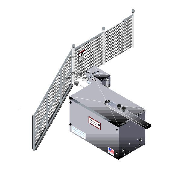
INSTALLATION LAYOUT HAND KNOBS FOR MANUAL DISCONNECT (USE HOLES SHOWN AS STARTING POSITION) NOTE: 1. Layout mounting post and electrical conduit locations TO DISCONNECT OPERATOR FOR 3/8" BOLT MANUAL OPERATION; REMOVE CONTROL ARM as shown in figures below. Excavate required area for HAND KNOBS AND SEPARATE 3/8"... -
Page 9: Operator Installation
TOP MOUNTING ANGLE 3. Install end fittings on connecting rod assembly and 21-1/2" attach one end of assembly to end of control arm 2" U-BOLTS 2" O.D. (MOUNTING POST) extension. See figure #7. BY OTHERS LOWER CONNECTING SWING GATE OPERATOR MOUNTING ROD (2 PCS.) SET SCREWS... - Page 10 Note: Adjustment can be made in (4) locations to 8. When the desired open and closed gate position have get desired closed position. Always start with been achieved, remove control arm extension from option “a” control arm. See figure #6. a) Move the gate bracket to left or right of the 36 9.
-
Page 11: Electrical Connections
ELECTRICAL CONNECTIONS 2. Connect incoming power lines and ground wire as WARNING- DO NOT APPLY POWER UNTIL TOLD TO DO shown below. SO. RISK OF SHOCK OR INJURY MAY RESULT! Hot leg (black) to BLACK; Neutral (white) to White: NOTE: Wiring to operator must use watertight materials in Ground to Ground Screw. -
Page 12: Limit Adjustment
LIMIT ADJUSTMENT PROCEDURE NOTE: Operator should be completely installed, mechanically and electrically, before attempting to ▲ WARNING: READ ENTIRE PROCEDURE BEFORE set limit switch cams (See Fig. 11). STARTING. TURN OFF MAIN POWER BEFORE MAKING ANY ADJUSTMENTS! NOTE: For master slave installation, travel time for the master operator must be set longer than the ▲... -
Page 13: Master/Slave Installation
CLOSE LIMIT SWITCH ADJUSTMENT: MASTER/SLAVE INSTALLATION NOTE: A single unit is considered a Master. In a 1. Press close button on control station, gate should stop Master/Slave installation, one unit must be converted to before full close position is reached. If gate does not stop LEFT HAND operation. -
Page 14: Timer To Close
MASTER ACCESORY CONTROL CONNECTIONS RADIO CONTROL INSTALLATION 13 14 16 17 A Three or Four wire radio control receiver can be installed on this operator. This radio control receiver can only be used to open the gate, therefore the “TIMER TO 13 14 16 17 CLOSE”... -
Page 15: Loop Detector Systems
LOOP DETECTOR SYSTEMS AND INSTALLATION LOOP INSTALLATION 1. Layout the desired loop locations per the diagram. The diagram below depicts the typical loop options for a standard size chart below will give Slide Gate installation. approximate length of wire required for various loop dimensions and number of turns required. - Page 16 2. Cut the required groove as shown in the diagram below 3. Leaving enough wire for the LEAD IN, insert the at the locations laid out in Step #1. specified number of turns of wire in the cut grooves. (See chart). CAUTION: Be careful not to damage the wire insulation during installation.
-
Page 17: Safety Device Connections
EXIT LOOP CONNECTION SAFETY DEVICE CONNECTIONS INHERENT OBSTRUCTION SENSING DEVICE: NOTE: The gate MUST move smoothly and easily in manual operation before attempting this adjustment. Not Used WARNING: TURN OFF POWER TO OPERATOR WHEN BK WH MAKING ANY ADJUSTMENTS. This unit is supplied with a current sensing system, which will stop the gate when it encounters an obstruction and then backs the gate off approximately 2 inches. -
Page 18: Secondary Obstruction Sensing Devices
SECONDARY OBSTRUCTION SENSING DEVICES 2. Connect contact sensor edges to the control board as shown in the illustration below. Another sensing device (Either a contact or a non-contact system) must be installed and connected to this unit to Outside Edge increase protection against entrapment per U/L requirements. - Page 19 NON-CONTACT SENSOR INSTALLATION 3. Connect NON-CONTACT sensors to the control board as shown below. 1. Install photoelectric cell as close to the full open NON CONTACT SENSOR CONNECTION position and full closed position of gate as possible. Align With Align With Reflector Reflector 2.
-
Page 20: Maintenance Log/Notes
Periodically check all hardware (nuts, bolts, screws, etc) for tightness. Limited 5 Year Warranty PowerMaster warrants all gate operators to be free of defects in Maintenance Log/Notes materials and workmanship for a period of Five (5) years from date ______________________________________________ of purchase. - Page 21 Maintenance Log/Notes Maintenance Log/Notes ______________________________________________ ______________________________________________ ______________________________________________ ______________________________________________ ______________________________________________ ______________________________________________ ______________________________________________ ______________________________________________ ______________________________________________ ______________________________________________ ______________________________________________ ______________________________________________ ______________________________________________ ______________________________________________ ______________________________________________ ______________________________________________ ______________________________________________ ______________________________________________ ______________________________________________ ______________________________________________ ______________________________________________ ______________________________________________ ______________________________________________ ______________________________________________ ______________________________________________ ______________________________________________ ______________________________________________ ______________________________________________ ______________________________________________ ______________________________________________ ______________________________________________ ______________________________________________ ______________________________________________ ______________________________________________ ______________________________________________ ______________________________________________ ______________________________________________ ______________________________________________ ______________________________________________...
- Page 22 ______________________________________________ Email to techsupport@power-master.net ______________________________________________ ______________________________________________ PowerMaster ______________________________________________ ______________________________________________ ______________________________________________ Registration Information ______________________________________________ ______________________________________________ Model RSW Location Installed: Date Installed____________ Address _______________ ______________________________________________ Serial # ________________ Address _______________ ______________________________________________ Address _______________ ______________________________________________ ______________________________________________ Installer’s Information ______________________________________________ Company Name _____________________________ ______________________________________________...
Need help?
Do you have a question about the rsw and is the answer not in the manual?
Questions and answers