Table of Contents
Advertisement
Advertisement
Table of Contents

Related Manuals for Icom IC-F3030 Series


Summary of Contents for Icom IC-F3030 Series
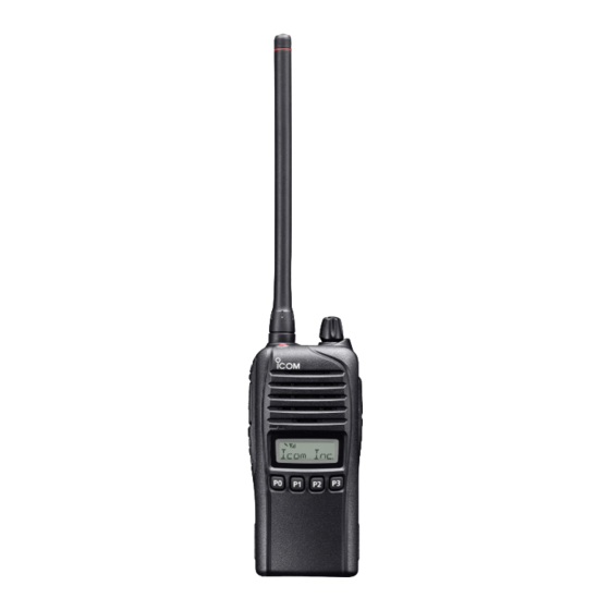
- Page 1 INSTRUCTION MANUAL VHF TRANSCEIVERS iF3030 Series UHF TRANSCEIVERS iF4030 Series This device complies with Part 15 of the FCC Rules. Operation is subject to the condition that this device does not cause harmful interference. The photo shows the VHF transceiver...
- Page 1 INSTRUCTION MANUAL VHF TRANSCEIVERS iF3030 Series UHF TRANSCEIVERS iF4030 Series This device complies with Part 15 of the FCC Rules. Operation is subject to the condition that this device does not cause harmful interference. The photo shows the VHF transceiver...
-
Page 2: Explicit Definitions
Dispose of them according to the laws in your area. Icom, Icom Inc. and Icom logo are registered trademarks of Icom Incorporated (Japan) in Japan, the United States, the United Kingdom, Germany, France, Spain, Russia, Australia, New Zealand, and/or other countries. -
Page 2: Explicit Definitions
FOREWORD RECOMMENDATION Thank you for choosing this Icom product. This product is designed CLEAN THE TRANSCEIVER THOROUGHLY WITH FRESH and built with Icom’s state of the art technology and craftsmanship. WATER after exposure to saltwater, and dry it before operating. -
Page 3: Precautions
Use and charge only specified Icom bat- tery pack and jack cover are securely attached to the radio, tery packs with Icom radios or Icom chargers. Only Icom bat- and that the antenna and battery pack are dry before attach- tery packs are tested and approved for use with Icom radios ment. -
Page 3: Precautions
Icom transceivers or Icom chargers. Only DO NOT operate the transceiver near unshielded Icom battery packs are tested and approved for use with electrical blast ing caps or in an explosive atmosphere. Icom transceivers or charged with Icom chargers. Using... -
Page 4: Fcc Information
MAKE SURE to turn OFF the radio power before CAUTION: Changes or modifications to this transceiver, connect ing the supplied/optional equipment. not expressly approved by Icom Inc., could void your au- thority to operate this transceiver under FCC regulations. -
Page 4: Fcc Information
• Force majeure, including, but not limited to, fires, earthquakes, storms, floods, lightnings, or other natural disasters, disturbances, riots, war, or radioactive contamination. • The use of Icom transceiver with any equipment that is not manufactured or approved by Icom. -
Page 5: Table Of Contents
TABLE OF CONTENTS 4 BATTERY CHARGING ..........15–19 IMPORTANT ................i ■ Caution ...............15 EXPLICIT DEFINITIONS ............i ■ Battery chargers ............17 PRECAUTIONS ..............ii FCC INFORMATION ............iii 5 OPTIONAL SWIVEL BELT CLIP ......20–21 TABLE OF CONTENTS ............iv ■ MB-93 contents ............20 ■... -
Page 5: Table Of Contents
TABLE OF CONTENTS 4 BATTERY CHARGING ..........15–19 FOREWORD ................. i IMPORTANT ................i ■ Caution ...............15 EXPLICIT DEFINITIONS ............i ■ Battery chargers ............17 RECOMMENDATION ............i 5 OPTIONAL SWIVEL BELT CLIP ......20–21 PRECAUTIONS ..............ii ■ MB-93 contents ............20 FCC INFORMATION ............ -
Page 6: Accessories
ACCESSORIES ■ Supplied accessories D Battery pack To attach the battery pack: Slide the battery pack in the direction of the arrow (q) until NOTE: Some accessories are not supplied with depending the battery release button makes a ‘click’ sound. on versions. -
Page 6: Accessories
ACCESSORIES ■ Supplied accessories D Battery pack To attach the battery pack: Slide the battery pack in the direction of the arrow (q) until NOTE: Some accessories are not supplied with depending the battery release button makes a ‘click’ sound. on versions. - Page 7 ACCESSORIES D Belt clip D Jack cover To attach the belt clip: To attach the jack cover: q Release the battery pack if it is attached. q Attach the jack cover to the [MIC/SP] jack. w Slide the belt clip in the direction of the arrow until the belt w Tighten the screws.
- Page 7 ACCESSORIES D Belt clip D Jack cover To attach the belt clip: To attach the jack cover: q Release the battery pack if it is attached. q Attach the jack cover to the [MIC/SP] jack. w Slide the belt clip in the direction of the arrow until the belt w Tighten the screws.
-
Page 8: Panel Description
PANEL DESCRIPTION ■ Front panel t DEALER-PROGRAMMABLE KEYS [Side2]/[Side3] D esired functions can be programmed independently by your dealer. (p. 5) y DEALER-PROGRAMMABLE KEYS [P0] to [P3] D esired functions can be programmed independently by your dealer. (p. 5) u FUNCTION DISPLAY (p. 4) Displays a variety of information such as an operating channel number/name, 2-Tone code, DTMF numbers, se- Speaker... -
Page 8: Panel Description
PANEL DESCRIPTION ■ Front panel t DEALER-PROGRAMMABLE KEYS [Side2]/[Side3] D esired functions can be programmed independently by your dealer. (p. 5) y DEALER-PROGRAMMABLE KEYS [P0] to [P3] D esired functions can be programmed independently by your dealer. (p. 5) u FUNCTION DISPLAY (p. 4) Displays a variety of information such as an operating channel number/name, 2-Tone code, DTMF numbers, Speaker... -
Page 9: Function Display
PANEL DESCRIPTION ■ Function display y SCRAMBLER INDICATOR Appears when the voice scrambler function is activated. u BELL INDICATOR A ppears or blinks when the specific 2-Tone code is re- ceived, according to the pre-programming. i KEY LOCK INDICATOR A ppears during the key lock function is ON. o BATTERY INDICATOR A ppears or blinks when the battery power decreases to a q TRANSMIT INDICATOR... -
Page 9: Function Display
PANEL DESCRIPTION ■ Function display y SCRAMBLER INDICATOR Displayed when the voice scrambler function is activated. u BELL INDICATOR D isplayed or blinks when the specific 2-Tone code is received, according to the pre-programming. i KEY LOCK INDICATOR Displayed during the key lock function is ON. o BATTERY INDICATOR D isplayed or blinks when the battery power decreases to a q TRANSMIT INDICATOR... -
Page 10: Programmable Function Keys
When the power ON scan function is turned OFF; Consult your Icom dealer or system operator for details con- cerning your transceivers programming. Push to start and cancel scanning operation. In case of transmission during scan, scanning will be cancelled. -
Page 10: Programmable Function Keys
When the power ON scan function is turned OFF: Consult your Icom dealer or system operator for details concerning your transceivers programming. Push to start and cancel scanning operation. In case of transmission during scan, scanning will be cancelled. - Page 11 PANEL DESCRIPTION SCAN ADD/DEL (TAG) KEY MR-CH 1/2/3/4 KEYS ➥ Push to add a channel to, or delete it from the current scan Push to select memory channels 1 to 4 in the operating zone list. directly. • When a channel is added to the current scan list, the display MONI KEY shows “SCAN ON.”...
- Page 11 PANEL DESCRIPTION SCAN ADD/DEL (TAG) KEY MR-CH 1/2/3/4 KEYS ➥ Push to add a channel to, or delete it from the current scan Push to select memory channels 1 to 4 in the operating zone list. directly. • When a channel is added to the current scan list, the display MONI KEY shows “SCAN ON.”...
-
Page 12: Panel Description
PANEL DESCRIPTION TALK AROUND KEY EMERGENCY KEY Push to turn the talk around function ON and OFF. Hold down to transmit the emergency call. • The talk around function equalizes the transmit frequency to the • The transceiver can transmit the emergency call silently or audibly receive frequency for transceiver-to-transceiver communication. -
Page 13: Basic Operation
BASIC OPERATION ■ Turning power ON D Battery type selection Prior to using the transceiver for the first time, the battery The battery type must be selected according to the type of pack must be fully charged for optimum life and operation. battery you are using when turning the transceiver ON. -
Page 13: Basic Operation
BASIC OPERATION ■ Turning power ON D Battery type selection Prior to using the transceiver for the first time, the The battery type must be selected according to the type of battery pack must be fully charged for optimum life and battery you are using when turning ON the transceiver. -
Page 14: Channel Selection
BASIC OPERATION ■ Channel selection ■ Call procedure Several types of channel selections are available. Methods When your system employs tone signaling (excluding CTCSS may differ according to your system set up. and DTCS), the call procedure may be necessary prior to voice transmission. -
Page 15: Receiving And Transmitting
BASIC OPERATION ■ Receiving and transmitting D Transmitting notes CAUTION: Transmitting without an antenna may damage the transceiver. Refer to page 1 for accessory attach- • Transmit inhibit function ments. The transceiver has several inhibit functions which restrict transmission under the following conditions: Receiving: - The channel is in mute condition (‘Inaudible’... -
Page 15: Receiving And Transmitting
BASIC OPERATION ■ Receiving and transmitting CAUTION: Transmitting without an antenna may damage D Transmitting notes the transceiver. Refer to page 1 for accessory attachments. • Transmit inhibit function The transceiver has several inhibit functions which restrict Receiving: transmission under the following conditions: q Rotate [VOL] to turn ON the transceiver. -
Page 16: D Tx Code Channel Selection
BASIC OPERATION D TX code channel selection D DTMF transmission If the transceiver has [TX Code CH Select] assigned to it, If the transceiver has [DTMF Autodial] assigned to it, the the indication can be toggled between the operating channel automatic DTMF transmission function is available. -
Page 17: User Set Mode
BASIC OPERATION ■ User set mode ■ Emergency Call You can “customize” the transceiver operation to suit your When [Emergency] is pushed for the specified time period*, preferences and operating style. the emergency signal is transmitted once, or repeatedly, on the specified emergency channel. -
Page 18: Priority A Channel Selection
BASIC OPERATION ■ Priority A channel selection ■ Stun function Depending on the presetting, the Priority A channel is se- When the specified ID, set as a stun ID or kill ID, is received, lected each time the transceiver power is turned ON. the stun function is activated. -
Page 18: Priority A Channel Selection
BASIC OPERATION ■ Priority A channel selection ■ Stun function Depending on the presetting, the Priority A channel is When the specified ID, set as a stun ID or kill ID, is received, selected each time the transceiver power is turned ON. the stun function is activated. -
Page 19: Mdc 1200 System Operation
BASIC OPERATION ■ MDC 1200 system operation D Receiving an Emergency Call The MDC 1200 signaling system enhances your transceiv- er’s capabilities. It allows PTT ID*, Emergency signaling, and q When an emergency call is received; receiving Radio Check. Also, the dispatcher can stun and re- •... -
Page 19: Mdc 1200 System Operation
BASIC OPERATION ■ MDC 1200 system operation The MDC 1200 signaling system enhances your D Receiving an Emergency Call transceiver’s capabilities. It allows PTT ID*, Emergency q When an emergency call is received: signaling, and receiving Radio Check. Also, the dispatcher •... -
Page 20: Battery Charging
If any of age may not be visible on the outside of the case. Even if the sur- these conditions occur, contact your Icom dealer or distributor. face of the battery pack does not show cracks or any other damage, R WARNING! Immediately wash, using clean water, any part of the the cells inside may rupture or catch fire. -
Page 20: Battery Charging
R DANGER! NEVER use or leave battery packs in areas with an abnormal odor, heats up, or is discolored or deformed. If any of these conditions occur, contact your Icom dealer or distributor. temperatures above +60˚C (+140˚F). High temperature buildup in... -
Page 21: D Charging Caution
• The battery has been repeatedly charged. +113˚F). BC-119N and BC121N (+10˚C to +40˚C; +50˚F to +104˚F). Icom recommends charging the battery at +20˚C (+68˚F). The bat- tery may heat up or rupture if charged out of the specified tempera- ture range. -
Page 21: D Charging Caution
BC-160 and BC-171 (0˚C to +45˚C: +32˚F to +113˚F). BC-119N and BC121N (+10˚C to +40˚C: +50˚F to +104˚F). Icom recommends charging the battery at +20˚C (+68˚F). The battery may heat up or rupture if charged out of the specified temperature range. -
Page 22: Battery Chargers
BATTERY CHARGING ■ Battery chargers D Rapid charging with the BC-160 D Regular charging with the BC-171 The supplied or optional BC-160 provides rapid charging of The optional BC-171 provides regular charging of the Li-ion the Li-ion battery pack. battery pack. The following item is additionally required: •... -
Page 22: Battery Chargers
BATTERY CHARGING ■ Battery chargers D Rapid charging with the BC-160 D Regular charging with the BC-171 The supplied or optional BC-160 provides rapid charging of The optional BC-171 provides regular charging of the Li-ion the Li-ion battery pack. battery pack. The following item is additionally required: •... - Page 23 BATTERY CHARGING D AD-106 installation D Rapid charging with the BC-119N+AD-106 The AD-106 must be installed into the BC- The optional BC-119N provides rapid charging of the Li-ion charger adapter 119N or BC-121N before battery charging. battery pack. The following items are additionally required. ➥...
- Page 23 BATTERY CHARGING D AD-106 installation D Rapid charging with the BC-119N+AD-106 The AD-106 must be installed into the BC- The optional BC-119N provides rapid charging of the Li-ion charger adapter 119N or BC-121N before battery charging. battery pack. The following items are additionally required. •...
- Page 24 BATTERY CHARGING D Rapid charging with the BC-121N+AD-106 The optional BC-121N allows up to 6 Li-ion battery packs to IMPORTANT: Battery charging caution be charged simultaneously. The following items are addition- Ensure the guide tabs on the battery pack are correctly ally required.
- Page 24 BATTERY CHARGING D Rapid charging with the BC-121N+AD-106 The optional BC-121N allows up to 6 Li-ion battery packs IMPORTANT: Battery charging caution to be charged simultaneously. The following items are Ensure the guide tabs on the battery pack are correctly additionally required.
-
Page 25: Optional Swivel Belt Clip
OPTIONAL SWIVEL BELT CLIP ■ MB-93 contents r Clip the belt clip to a part of your belt. And insert the trans- ceiver into the belt clip until the base clip inserted fully into the groove. Qty. q Belt clip ................1 w Base clip .................1 ■... -
Page 25: Optional Swivel Belt Clip
OPTIONAL SWIVEL BELT CLIP ■ MB-93 contents r Clip the belt clip to a part of your belt. And insert the trans- ceiver into the belt clip until the base clip inserted fully into the groove. Qty. q Belt clip ................1 w Base clip .................1 ■... -
Page 26: Detaching
OPTIONAL SWIVEL BELT CLIP ■ Detaching q Turn the transceiver upside down in the direction of the w Release the battery pack if it is attached. (p. 2) e Pinch the clip (q), and slide the base clip in the direction arrow and pull out from the belt clip. -
Page 26: Detaching
OPTIONAL SWIVEL BELT CLIP ■ Detaching q Turn the transceiver upside down in the direction of the w Release the battery pack if it is attached. (p. 2) e Pinch the clip (q), and slide the base clip in the direction arrow and pull out from the belt clip. -
Page 27: Speaker Microphone
SPEAKER MICROPHONE ■ Optional HM-168LWP description ■ Attachment Attach the connector of the speaker-microphone into the [SP Alligator type clip MIC] jack on the transceiver and tighten the screws with fin- To attach the speaker-mic. gers. to your shirt or collar, etc. NOTE: Use only your fingers instead of tools to tighten the screws. -
Page 28: Battery Case
BATTERY CASE ■ BP-240 optional battery case When using the BP-240 battery case, install six AAA (LR03) Fig.1 size alkaline batteries, as illustrated to the right. The BP-240 BP-240 is constructed to the IPX4 waterproof standard. q Unhook the battery cover release hook (q), and open the cover in the direction of the arrow (w). -
Page 29: Bp-261 Optional Battery Case
BATTERY CASE ■ BP-261 optional battery case D Alkaline batteries installation BP-261 Install six AA (LR6) size alkaline batteries as described below. The BP-261 is constructed to the IPX4 waterproof standard. q Unhook the battery cover release hook (q), and open the cover in the direction of the arrow (w). -
Page 29: Bp-261 Optional Battery Case
BATTERY CASE ■ BP-261 optional battery case D Alkaline batteries installation BP-261 Install six AA (LR6) size alkaline batteries as described below. The BP-261 is constructed to the IPX4 waterproof standard. q Unhook the battery cover release hook (q), and open the Fig.1 cover in the direction of the arrow (w). - Page 30 BATTERY CASE D Battery case attachment Slide the battery pack in the direction of the arrow until the To release the battery case: battery release button makes a ‘click’ sound. Slide the battery case’s battery release button in the direction of the arrow (q), and then push the release button in the di- rection of the arrow (w).
- Page 30 BATTERY CASE D Battery case attachment Slide the battery pack in the direction of the arrow until the To release the battery case: battery release button makes a ‘click’ sound. Slide the battery case’s battery release button in the direction of the arrow (q), and then push the release button in the di- rection of the arrow (w).
-
Page 31: Options
OPTIONS D BATTERY PACK • BC-160 + BC-145S desktop charger ac adapter For rapid charging of battery packs. A power adapter is sup- Battery pack Voltage Capacity Battery life* plied with the charger depending on versions. 2250 mAh (min.) Charging time: Approximately 3.5 hours for the BP-232WP BP-232WP 7.4 V 17.5 hrs. -
Page 31: Options
OPTIONS D BATTERY PACK • BC-160 + BC-145S desktop charger ac adapter For rapid charging of battery packs. A power adapter is sup- Battery pack Voltage Capacity Battery life* plied with the charger depending on versions. 2250 mAh (min.) Charging time: Approximately 3.5 hours for the BP-232WP BP-232WP 7.4 V 17.5 hrs. - Page 32 Icom transceiver. Non-rolling type (UT-109R)/Rolling type (UT-110R*) voice Icom is not responsible for the destruction or damage to an scrambler unit provides higher communication security. Icom transceiver in the event the Icom transceiver is used with *You can use the UT-110R as Non-rolling type.
- Page 32 OPTIONS D OPTIONAL UNITS • UT-96R Some options may not be available in some countries. Ask tone unit • UT-108R your dealer for details. dtmf decoder unit Provides pager and code squelch capabilities. • UT-109R /UT-110R* voice scrambler units Non-rolling type (UT-109R)/Rolling type (UT-110R*) voice scrambler unit provides higher communication security.
-
Page 33: Safety Training Information
This radio has been tested and complies with the FCC RF exposure FCC RF exposure compliance requirements to be exceeded. limits for “Occupational Use Only”. In addition, your Icom radio com- The radio is transmitting when the TX indicator lights red. You plies with the following Standards and Guidelines with regard to RF can cause the radio to transmit by pressing the “PTT”... -
Page 33: Safety Training Information
This radio has been tested and complies with the FCC RF exposure FCC RF exposure compliance requirements to be exceeded. limits for “Occupational Use Only”. In addition, your Icom radio com- The radio is transmitting when the TX indicator lights red. You plies with the following Standards and Guidelines with regard to RF can cause the radio to transmit by pressing the “PTT”... - Page 34 • Norme de l’ANSI: IEEE C95.3-1992 sur la méthode d’évaluation re- Interférence électromagnétique et compatibilité commandée du champ magnétique potentiellement dangereux des En mode de transmission, votre radio Icom produit de l’énergie de RF qui radiofréquences et des micro-ondes. peut provoquer des interférences avec d’autres appareils ou systèmes. Pour •...
- Page 34 • Norme de l’ANSI: IEEE C95.3-1992 sur la méthode d’évaluation re- Interférence électromagnétique et compatibilité commandée du champ magnétique potentiellement dangereux des En mode de transmission, votre radio Icom produit de l’énergie de RF qui radiofréquences et des micro-ondes. peut provoquer des interférences avec d’autres appareils ou systèmes. Pour •...
- Page 35 MEMO...
- Page 35 MEMO...
- Page 36 MEMO...
- Page 36 MEMO...
- Page 37 MEMO...
- Page 37 MEMO...
- Page 38 MEMO...
- Page 38 MEMO...
- Page 39 MEMO...
- Page 39 MEMO...
- Page 40 A-6995D-1EX-t Printed in Japan © 2012–2016 Icom Inc. 1-1-32 Kamiminami, Hirano-ku, Osaka 547-0003, Japan Printed on recycled paper with soy ink.
- Page 40 A-6995D-1EX-r Printed in Japan © 2012–2015 Icom Inc. 1-1-32 Kamiminami, Hirano-ku, Osaka 547-0003, Japan Printed on recycled paper with soy ink.
Need help?
Do you have a question about the IC-F3030 Series and is the answer not in the manual?
Questions and answers