Icom IC-F3011 Instruction Manual
Vhf/uhf transceivers
Hide thumbs
Also See for IC-F3011:
- Price list (158 pages) ,
- Instruction manual (48 pages) ,
- Service manual addendum (39 pages)

Subscribe to Our Youtube Channel
Related Manuals for Icom IC-F3011


Summary of Contents for Icom IC-F3011
- Page 1 INSTRUCTION MANUAL VHF TRANSCEIVERS iF3011 iF3013 UHF TRANSCEIVERS iF4011 iF4013 This device complies with Part 15 of the FCC Rules. Operation is subject to the condition that this device does not cause harmful inter- ference.
-
Page 2: Safety Training Information
“General Population” in an uncontrolled environment. This radio has been tested and complies with the FCC RF exposure limits for “Occupational Use Only”. In addition, your Icom radio complies with the following Standards and Guidelines with regard to RF energy and electromagnetic energy levels and evaluation of such levels for exposure to humans: •... - Page 3 “PTT” switch or VOX function. • ALWAYS keep the antenna at least 2.5 cm (1 inch) away from the body when transmitting and only use the Icom belt-clip which is listed on page 33 when attaching the radio to your belt, etc., to en- sure FCC RF exposure compliance requirements are not exceeded.
-
Page 4: Explicit Definitions
If disregarded, inconvenience only. No risk NOTE of personal injury, fire or electric shock. Icom, Icom Inc. and the Icom logo are registered trademarks of Icom Incorpo- rated (Japan) in Japan, the United States, the United Kingdom, Germany, France, Spain, Russia and/or other countries. -
Page 5: Precautions
The use of non-Icom battery packs/chargers may impair trans- ceiver performance and invalidate the warranty. For U.S.A. only CAUTION! Changes or modifications to this device, not expressly approved by Icom Inc., could void your authority to operate this transceiver under FCC regulations. -
Page 6: Table Of Contents
TABLE OF CONTENTS SAFETY TRAINING INFORMATION ............ i FOREWORD ..................iii EXPLICIT DEFINITIONS ..............iii PRECAUTIONS .................. iv TABLE OF CONTENTS ............... v 1 ACCESSORIES ................. 1–5 ■ Supplied accessories ..............1 ■ Accessory attachments .............. 2 2 PANEL DESCRIPTION ............6–11 ■... -
Page 7: Accessories
ACCESSORIES ■ Supplied accessories The following accessories are supplied. Flexible Battery pack Battery carger antenna* (with AC adapter) Jack cover (with screws) Belt clip *This illustration is described with the VHF type. -
Page 8: Accessory Attachments
ACCESSORIES ■ Accessory attachments D Flexible antenna Connect the supplied flexible antenna to the antenna connector. CAUTION: • NEVER HOLD the antenna when carrying the transceiver. • Transmitting without an antenna may damage the transceiver. -
Page 9: D Battery Pack
ACCESSORIES D Battery pack To attach the battery pack: Slide the battery pack on the back of the transceiver in the direction of the arrow (q), then lock it with the battery release button. • Slide the battery pack until the battery release button makes a ‘click’ sound. -
Page 10: D Jack Cover
ACCESSORIES D Jack cover Attach the jack cover when the optional speaker-microphone is not used. To attach the jack cover: To detach the jack cover: q Attach the jack cover to the e Unscrew the screws with a [SP MIC] connector. phillips screwdriver. -
Page 11: Accessories
ACCESSORIES D Belt clip To attach the belt clip: q Release the battery pack if it is attached. w Slide the belt clip in the direction of the arrow until the belt clip is locked and makes a ‘click’ sound. To detach the belt clip: q Release the battery pack if it is attached. -
Page 12: Panel Description
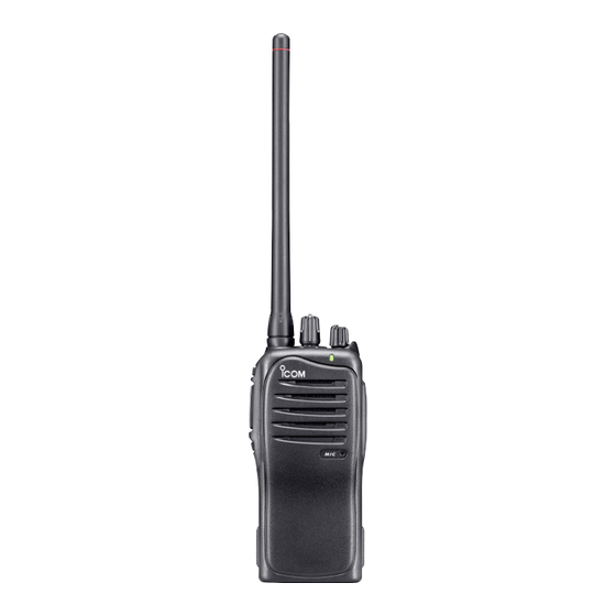
PANEL DESCRIPTION ■ Front, top and side panels Speaker Microphone q CHANNEL SELECTOR Rotate the channel selector to select the pre-programmed mem- ory channels. w VOLUME CONTROL [VOL] Rotate to turn the power ON/OFF and adjust the audio level. - Page 13 PANEL DESCRIPTION e LED INDICATOR (p. 8) ➥ Lights red while transmitting. ➥ Lights green while receiving a signal, or when the squelch is open. ➥ Lights/blinks orange when the matched 2/5-tone code is re- ceived, according to the pre-programming. (For IC-F3013/ F4013 only) r SPEAKER-MICROPHONE CONNECTOR [SP MIC] Connects the optional speaker-microphone, earphone, etc.
-
Page 14: Led Indicator
PANEL DESCRIPTION ■ LED indicator The LED indicator indicates several information as follows; (Ref.; R=Red, G=Green, O=Orange) • TX: Turns Red while transmitting a signal. • RX: Turns Green while receiving a signal. • Fast/Slow scan: Blinks while Fast/Slow scan is activated. c an •... -
Page 15: Programmable Function Keys
PANEL DESCRIPTION ■ Programmable function keys The following functions can be assigned to [Upper] and [Lower] programmable function keys. Consult your Icom dealer or system operator for details concerning your transceivers programming. D For All models SCAN A KEY ➥ Push to start and cancel scanning operation. - Page 16 PANEL DESCRIPTION OUTPUT POWER SELECTION KEY Select the transmit output power temporarily or permanently, de- pending on the pre-setting. • Ask your dealer for the output power level for each selection. TALK AROUND KEY ➥ Push to turn the talk around function OFF. ➥...
- Page 17 PANEL DESCRIPTION MONITOR KEY ➥ Push to mute and release the CTCSS (DTCS) or 2Tone* squelch mute. Open any squelches/deactivate any mutes while pushing this key. (LMR operation only) * Available for the IC-F3013/F4013 only. ➥ Activates one of (or two of) the following functions on each chan- nel independently: (PMR operation only) •...
-
Page 18: Conventional Operation
CONVENTIONAL OPERATION ■ Turning power ON Rotate [VOL] to turn power ON. [VOL] ■ Channel selection Rotate [CHANNEL SELECTOR] to se- [CHANNEL SELECTOR] lect the desired operating channel, in sequence; or, push one of [MR-CH 1] to [MR-CH 4] key to select a channel di- rectly. -
Page 19: Receiving And Transmitting
CONVENTIONAL OPERATION ■ Receiving and transmitting NOTE: Transmitting without an antenna may damage the trans- ceiver. See p. 2 for antenna attachment. Receiving: q Rotate [VOL] to turn power ON. w Rotate [CHANNEL SELECTOR] or push one of [MR-CH 1] to [MR-CH 4] key to select a channel. -
Page 20: D Transmitting Notes
CONVENTIONAL OPERATION D Transmitting notes • Transmit inhibit function The transceiver has several inhibit functions which restrict trans- mission under the following conditions: - The channel is in mute condition. - The channel is busy. - Un-matched (or matched) CTCSS is received. - The selected channel is a ‘receive only’... -
Page 21: Setting The Squelch Level
CONVENTIONAL OPERATION ■ Setting the squelch level The squelch circuit mutes the received audio signal depending on the signal strength. [VOL] q While pushing [PTT] and [Lower], rotate [VOL] to turn the power ON to enter the squelch level adjust- ment mode. -
Page 22: Signaling Operations
SIGNALING OPERATIONS NOTE: The tone signalling operations are available for the IC-F3013/F4013 only. ■ Call procedure When your system employs tone signalling (excluding CTCSS and DTCS), the call procedure may be necessary prior to voice trans- mission. The tone signalling employed may be a selective calling system which allows you to call specific station(s) only and prevent unwanted stations from contacting you. -
Page 23: Emergency Call
SIGNALING OPERATIONS ■ Emergency Call When [Emergency Single] or [Emergency Repeat] (p. 11) is pushed and held for the specified time period, the emergency sig- nal (5-tone, DTMF or MDC 1200) is transmitted once or repeatedly on the emergency channel. A repeat emergency signal is auto- matically transmitted until it receives the acknowledgement signal. -
Page 24: Battery Charging
R DANGER! Use and charge only specified Icom battery packs with Icom radios or Icom charger. Only Icom battery packs are tested and approved for use and charge with Icom radios or Icom charger. Using third-party or counterfeit battery packs or charger may cause smoke, fire, or cause the battery to burst. - Page 25 WARNING! Immediately stop using the battery if it emits an ab- normal odor, heats up, or is discolored or deformed. If any of these conditions occur, contact your Icom dealer or distributor. WARNING! Immediately wash, using clean water, any part of the body that comes into contact with fluid from inside the battery.
-
Page 26: D Charging Caution
CAUTION! DO NOT charge the battery outside of the specified temperature range: BC-160 (0˚C to +40˚C; +32˚F to +104˚F). Icom recommends charging the battery at +20˚C (+68˚F). The battery may heat up or rupture if charged out of the specified temperature range. -
Page 27: Battery Chargers
BATTERY CHARGING ■ Battery chargers D Rapid charging with the BC-160 The optional BC-160 provides rapid charging of the Li-Ion battery pack. Charging period: Approx. 3 hours (with BP-232N) The following items are additionally required: • An AC adapter (not supplied with some versions) or the DC power cable (OPC-515L/CP-17L) is additionally required. -
Page 28: Regular Charging With The Bc
BATTERY CHARGING D Regular charging with the BC-171 The optional BC-171 provides regular charging of the Li-Ion battery pack. Charging period: Approx. 10 hours (with BP-232N) The following items are additionally required: • An AC adapter (not supplied with some versions) or the DC power cable (OPC-515L/CP-17L) is additionally required. - Page 29 BATTERY CHARGING D AD-106 installation The AD-106 must be installed into the BC-119N charger adapter or BC-121N before battery charging. ➥ Connect the AD-106 and the BC-119N/BC- charger adapter 121N as below, then install the AD-106 into the holder space of the BC-119N or BC-121N with the supplied screws.
- Page 30 BATTERY CHARGING D Rapid charging with the BC-119N+AD-106 The optional BC-119N provides rapid charging of the Li-Ion battery pack. Charging period: Approx. 3 hours (with BP-232N) The following items are additionally required: • An AD-106 (purchase separately) • An AC adapter (not supplied with some versions) or the DC power cable (OPC-515L/CP-17L).
-
Page 31: Battery Charging
BATTERY CHARGING D Rapid charging with the BC-121N+AD-106 The optional BC-121N allows up to 6 battery packs to be charged simultaneously. Charging period: Approx. 3 hours (with BP-232N) The following items are additionally required. • Six AD-106. • An AC adapter (BC-157) or the DC power cable (OPC-656) Transceiver Turn power OFF Battery pack... -
Page 32: Battery Case
BATTERY CASE ■ Optional battery case (BP-240) When using the optional battery case, install 6 × AAA (LR03) size alkaline batteries as illustrated at right. q Unhook the battery cover release hook (q), and open the cover in the direction of the arrow (w). (Fig.1) w Then, install 6 ×... - Page 33 BATTERY CASE Fig.1 BP-240 Fig.2 Fig.3...
-
Page 34: Swivel Belt Clip
SWIVEL BELT CLIP ■ MB-93 contents Qty. q Belt clip ..................1 w Base clip .................. 1 ■ To attach q Release the battery pack if it is attached. (p. 3) w Slide the base clip in the direction of the arrow until the base clip is locked and makes a ‘click’... - Page 35 SWIVEL BELT CLIP e Clip the belt clip to a part of your belt. And insert the transceiver into the belt clip until the base clip inserted fully into the groove. r Once the transceiver is locked in place, it swivels as illustrated below.
-
Page 36: To Detach
SWIVEL BELT CLIP ■ To detach q Turn the transceiver upside down in the direction of the arrow and pull out from the belt clip. -
Page 37: Swivel Belt Clip
SWIVEL BELT CLIP w Release the battery pack if it is attached. (p. 3) e Pinch the clip (q), and slide the base clip in the direction of the arrow (w). CAUTION: HOLD THE TRANSCEIVER TIGHTLY, WHEN HANGING OR DETACHING THE TRANSCEIVER FROM THE BELT CLIP. Otherwise the transceiver may not be attached to the holder or swivel properly if the transceiver is accidentally dropped and the base clip is scratched or damaged. -
Page 38: Options
OPTIONS D BATTERY PACK Battery pack Voltage Capacity Battery life* 950 mAh (min.) BP-230N 7.4 V 9 hrs. 980 mAh (typ.) 1900 mAh (min.) BP-232N 7.4 V 18 hrs. 2000 mAh (typ.) Battery case for AAA BP-240 —* (LR03) × 6 alkaline When the power save function is turned ON, and the operating pe- riods are calculated under the following conditions;... - Page 39 OPTIONS • BC-171 + BC-147S desktop charger ac adapter For regular charging of battery packs. We recommend that the BP-230N charging. An AC adapter is supplied with the charger depending on versions. Charging time: Approx. 10 hours when BP-232N is attached. Approx.
- Page 40 Icom optional equipment are designed for optimal performance when used with this transceiver. We are not responsible for the transceiver being damaged or any accident caused when using non-Icom optional equipment. Some options may not be available in some countries. Please ask your...
-
Page 41: Options
OPTIONS D About VS-1L ptt case The VS-1L is a VOX/PTT unit for Icom handheld transceivers, and allows you hands-free operation. An optional headset (HS-94, etc.) is additionally required for opera- tion. • The VOX (voice operated transmission) function starts transmission without pushing PTT switch when you speak into the microphone;... -
Page 42: Fcc Information
FCC INFORMATION • FOR CLASS B UNINTENTIONAL RADIATORS: This equipment has been tested and found to comply with the limits for a Class B digital device, pursuant to part 15 of the FCC Rules. These limits are designed to provide reasonable protection against harmful interference in a residential installation. - Page 43 MEMO...
- Page 44 MEMO...
- Page 45 MEMO...
- Page 46 MEMO...
- Page 47 MEMO...
- Page 48 A-6768H-1EX Printed in Japan © 2009 Icom Inc. 1-1-32 Kamiminami, Hirano-ku, Osaka 547-0003, Japan Printed on recycled paper with soy ink.
Need help?
Do you have a question about the IC-F3011 and is the answer not in the manual?
Questions and answers