Icom iC-F3033S Instruction Manual
Hide thumbs
Also See for iC-F3033S:
- Service manual addendum (105 pages) ,
- Instruction manual (40 pages) ,
- Instruction manual (32 pages)
Table of Contents
Advertisement
Quick Links
Advertisement
Table of Contents

Subscribe to Our Youtube Channel
Related Manuals for Icom iC-F3033S


Summary of Contents for Icom iC-F3033S
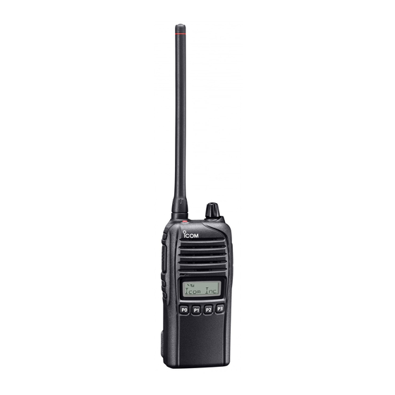
- Page 1 INSTRUCTION MANUAL VHF TRANSCEIVERS iF3031S iF3033S iF3036S UHF TRANSCEIVERS iF4031S iF4033S iF4036S This device complies with Part 15 of the FCC Rules. Operation is subject to the condition that this device does not cause harmful interference. The photo shows the VHF transceiver...
-
Page 2: Explicit Definitions
Son exploitation est autorisée sous réserve que l’appareil ne cause pas de brouillage préjudiciable. Icom, Icom Inc. and the Icom logo are registered trademarks of Icom Incor- porated (Japan) in Japan, the United States, the United Kingdom, Germany, France, Spain, Russia and/or other countries. -
Page 3: Precautions
Use and charge only specified Icom bat- attachment. Exposing the inside of the transceiver to dust or tery packs with Icom radios or Icom chargers. Only Icom bat- water will result in serious damage to the transceiver. tery packs are tested and approved for use with Icom radios... -
Page 4: Fcc Information
MAKE SURE to turn the transceiver power OFF before connect ing the supplied/optional equipment. For U.S.A. only: CAUTION: Changes or modifications to this transceiver, not expressly approved by Icom Inc., could void your authority to operate this transceiver under FCC regulations. -
Page 5: Table Of Contents
TABLE OF CONTENTS 4 BATTERY CHARGING ..........15–19 IMPORTANT ................i Caution ...............15 EXPLICIT DEFINITIONS ............i Optional battery chargers ...........17 PRECAUTIONS ..............ii FCC INFORMATION ............iii 5 OPTIONAL SWIVEL BELT CLIP ......20–21 TABLE OF CONTENTS ............iv MB-93 contents ............20 Attaching ..............20 1 ACCESSORIES ............1–2 Detaching ..............21... -
Page 6: Accessories
ACCESSORIES Supplied accessories Battery pack To attach the battery pack: Slide the battery pack in the direction of the arrow (q) until NOTE: Some accessories are not supplied with depending the battery release button makes a ‘click’ sound. on versions. NOTE: Push on the bottom of the pack to make sure the Battery pack release button is firmly locked. - Page 7 ACCESSORIES Belt clip Jack cover To attach the belt clip: To attach the jack cover: Release the battery pack if it is attached. q Attach the jack cover to the [MIC/SP] jack. w Slide the belt clip in the direction of the arrow until the belt w Tighten the screws.
-
Page 8: Panel Description
PANEL DESCRIPTION Front panel t DEALER-PROGRAMMABLE KEYS [Side2]/[Side3] Desired functions can be programmed independently by your dealer. (p. 5) y DEALER-PROGRAMMABLE KEYS [P0] to [P3] Desired functions can be programmed independently by your dealer. (p. 5) u FUNCTION DISPLAY (p. 4) Displays a variety of information such as an operating channel number/name, 2-tone code, DTMF numbers, se- Speaker... -
Page 9: Function Display
PANEL DESCRIPTION Function display y SCRAMBLER INDICATOR Appears when the voice scrambler function is activated. u BELL INDICATOR Appears or blinks when the specific 2-tone code is re- ceived, according to the pre-programming. i KEY LOCK INDICATOR Appears during the key lock function is ON. o BATTERY INDICATOR Appears or blinks when the battery power decreases to a q TRANSMIT INDICATOR... -
Page 10: Programmable Function Keys
When the power ON scan function is turned OFF; Consult your Icom dealer or system operator for details con- cerning your transceivers programming. Push to start and cancel scanning operation. In case of transmission during scan, scanning will be cancelled. - Page 11 PANEL DESCRIPTION SCAN ADD/DEL (TAG) KEY MR-CH 1/2/3/4 KEYS Push to add a channel to, or delete it from the current scan Push to select memory channels 1 to 4 in the operating zone list. directly. MONI KEY shows “SCAN ON.” When a channel is deleted from the current Mute and release the CTCSS (DTCS) or 2-tone squelch scan list, the display shows “SCAN OFF.”...
- Page 12 PANEL DESCRIPTION TALK AROUND KEY EMERGENCY KEY Push to turn the talk around function ON and OFF. Push and hold to transmit the emergency call. receive frequency for transceiver-to-transceiver communication. depending on the presetting. Ask your dealer for details. WIDE/NARROW KEY text is displayed on the LCD if programmed.
-
Page 13: Basic Operation
BASIC OPERATION Turning power ON Battery type selection Prior to using the transceiver for the first time, the battery The battery type must be selected according to the attaching pack must be fully charged for optimum life and operation. battery type when turning the transceiver ON. (p. -
Page 14: Channel Selection
BASIC OPERATION Channel selection Call procedure Several types of channel selections are available. Methods When your system employs tone signaling (excluding CTCSS may differ according to your system set up. and DTCS), the call procedure may be necessary prior to voice transmission. -
Page 15: Receiving And Transmitting
BASIC OPERATION Receiving and transmitting Transmitting notes CAUTION: Transmitting without an antenna may damage the transceiver. See page 1 for accessory attachments. The transceiver has several inhibit functions which restrict Receiving: transmission under the following conditions: Rotate [VOL] to turn the power ON. - The channel is in mute condition (‘Inaudible’... - Page 16 BASIC OPERATION TX code channel selection DTMF transmission If the transceiver has [TX Code CH Select] assigned to it, If the transceiver has [DTMF Autodial] assigned to it, the the indication can be toggled between the operating channel automatic DTMF transmission function is available. Up to 8 number (or name) and TX code channel number (or name).
-
Page 17: User Set Mode
BASIC OPERATION User set mode Emergency Call User set mode is accessed at power ON and allows you to When [Emergency] is pushed for the specified time period*, the emergency signal is transmitted once, or repeatedly, on the specified set seldom-changed settings. In this case you can “custom- emergency channel. -
Page 18: Priority A Channel Selection
BASIC OPERATION Priority A channel selection Stun function Depending on the presetting, the Priority A channel is se- When the specified ID, set as a stun ID or kill ID, is received, lected each time the transceiver power is turned ON. the stun function is activated. -
Page 19: Mdc 1200 System Operation
BASIC OPERATION MDC 1200 system operation Receiving an Emergency Call The MDC 1200 signaling system enhances your transceiv- er’s capabilities. It allows PTT ID*, Emergency signaling, and When an emergency call is received; receiving Radio Check. Also, the dispatcher can stun and re- vive transceivers on the system. -
Page 20: Battery Charging
Icom radios or Icom charger. Only Icom battery water, or any other liquids. Never charge or use a wet battery. packs are tested and approved for use and charge with Icom If the battery gets wet, be sure to wipe it dry before using. - Page 21 If R DANGER! NEVER charge the battery pack in areas with any of these conditions occur, contact your Icom dealer or extremely high temperatures, such as near fires or stoves, distributor.
-
Page 22: Optional Battery Chargers
BATTERY CHARGING Optional battery chargers Rapid charging with the BC-160 Regular charging with the BC-171 The optional BC-160 provides rapid charging of the Li-ion The optional BC-171 provides regular charging of the Li-ion battery pack. battery pack. sion) or the DC power cable (OPC-515L/CP-23L) is additionally sion) or the DC power cable (OPC-515L/CP-23L) is additionally required. - Page 23 BATTERY CHARGING AD-106 installation Rapid charging with the BC-119N+AD-106 The AD-106 must be installed into the BC- The optional BC-119N provides rapid charging of the Li-ion CHARGER ADAPTER 119N or BC-121N before battery charging. battery pack. The following items are additionally required. Connect the AD-106 and the BC-119N/ CHARGER ADAPTER...
- Page 24 BATTERY CHARGING Rapid charging with the BC-121N+AD-106 The optional BC-121N allows up to 6 Li-ion battery packs to IMPORTANT: Battery charging caution be charged simultaneously. The following items are addition- Ensure the guide tabs on the battery pack are correctly ally required.
-
Page 25: Optional Swivel Belt Clip
OPTIONAL SWIVEL BELT CLIP MB-93 contents r Clip the belt clip to a part of your belt. And insert the trans- ceiver into the belt clip until the base clip inserted fully into the groove. Qty. q Belt clip ................1 w Base clip .................1 Attaching Release the battery pack if it is attached. -
Page 26: Detaching
OPTIONAL SWIVEL BELT CLIP Detaching q Turn the transceiver upside down in the direction of the Release the battery pack if it is attached. (p. 2) e Pinch the clip (q), and slide the base clip in the direction arrow and pull out from the belt clip. of the arrow (w). -
Page 27: Speaker Microphone
SPEAKER MICROPHONE Optional HM-168LWP description Attachment Attach the connector of the speaker-microphone into the [SP Alligator type clip MIC] jack on the transceiver and tighten the screws with fin- To attach the speaker-mic. gers. to your shirt or collar, etc. NOTE: Use only your fingers instead of tools to tighten the screws. -
Page 28: Options
OPTIONS BATTERY PACK + BC-147S DESKTOP CHARGER AC ADAPTER Battery pack Voltage Capacity Battery life* An AC adapter is supplied with the charger depending on 2250 mAh (min.) versions. BP-232WP 7.4 V 17.5 hrs. 2300 mAh (typ.) Charging time: approximately 10 hours when BC-232WP is at- tached. - Page 29 Icom transceiver. Non-rolling type (UT-109R)/Rolling type (UT-110R)* voice Icom is not responsible for the destruction or damage to an scrambler unit provides higher communication security. Icom transceiver in the event the Icom transceiver is used with *You can use the UT-110R as Non-rolling type.
-
Page 30: Safety Training Information
This radio has been tested and complies with the FCC RF exposure FCC RF exposure compliance requirements to be exceeded. limits for “Occupational Use Only”. In addition, your Icom radio com- The radio is transmitting when the TX indicator lights red. You plies with the following Standards and Guidelines with regard to RF can cause the radio to transmit by pressing the “PTT”... - Page 31 FCC. Interférence électromagnétique et compatibilité commandée du champ magnétique potentiellement dangereux des En mode de transmission, votre radio Icom produit de l’énergie de RF qui radiofréquences et des micro-ondes. peut provoquer des interférences avec d’autres appareils ou systèmes. Pour Les accessoires illustrés à...
- Page 32 A-6995D-1EX Printed in Japan © 2012 Icom Inc. 1-1-32 Kamiminami, Hirano-ku, Osaka 547-0003, Japan Printed on recycled paper with soy ink.
Need help?
Do you have a question about the iC-F3033S and is the answer not in the manual?
Questions and answers