
Related Manuals for WAGNER P20 0552488


Summary of Contents for WAGNER P20 0552488
- Page 1 Operating manual Airless high-pressure spraying unit Models: 0552488 0552490 Edition 8 / 2012 0552 874B...
- Page 2 Before any work is done on the unit or for every break in work the following rules must be observed: 1. Release the pressure from spray gun and hose. 2. Secure the WAGNER spray gun using the safety catch on the trigger. 3. Switch off unit. Be safety conscious!
-
Page 3: Table Of Contents
Spare parts list of frame ..................28 High-pressure hose................10 Spare parts list for suction system ..............29 Interruption of work ................10 WAGNER-Service companies...............30 Cleaning the unit (shutting down) ..........10 Important notes on product liability ............32 3+2 years guarantee for professional finishing ........32 Cleaning unit from outside ..............10... -
Page 4: Safety Regulations For Airless Spraying
Safety Regulations Safety regulations for Airless spraying • ALWAYS remove the spray tip before flushing or cleaning the system. Explanation of symbols used • The paint hose can develop leaks from wear, kinking and abuse. A leak can inject material into the skin. Inspect the This manual contains information that must be read and understood hose before each use. before using the equipment. -
Page 5: Earthing Instructions
Vapors can cause severe nausea, fainting, or For reasons of function, safety and durability use poisoning. only original WAGNER high-pressure hoses. PREVENTION: • Use a respirator or mask if vapors can be inhaled. Read all instructions supplied with the mask to be sure it will provide Earthing Instructions the necessary protection. -
Page 6: General View Of Application
When the coating material exits from component coating materials, dispersions, latex paints. the tip it atomizes. No other materials should be used for spraying without WAGNER’s The pressure control knob controls the volume and the operating approval. -
Page 7: Legend For Explanatory Diagram P20
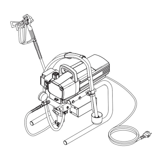
Description of unit Legend for explanatory diagram P20 1 Spray gun 8 Relief valve Lever position vertical – PRIME ( k circulation) 2 High-pressure hose 3 Return hose Lever position horizontal – SPRAY ( p) 4 Suction hose 9 Pressure control knob 5 Frame 10 ON/OFF switch 6 Drip cup 11 Circuit breaker 7 Power cord... -
Page 8: Technical Data
Description of unit Starting operation Technical data 5. Fill the oil cup with EasyGlide (Fig. 3). Do not use too much EasyGlide, i.e. ensure that no EasyGlide drips into the coating Voltage: 100~110 Volt AC, 50/60 Hz material container. Max. current consumption: 9.5 A @ 110VAC Power cord: 3 x 1.5 mm –... -
Page 9: Taking The Unit Into Operation With Coating Material
Spraying Technique Spraying technique Injection hazard. Do not spray without the tip guard in place. NEVER trigger the gun unless the tip is completely turned to either the spray or the unclog position. ALWAyS engage the gun trigger lock before removing, replacing or cleaning tip. The key to a good paint job is an even coating over the entire surface. -
Page 10: Handling The High-Pressure Hose
2. Close the relief valve, valve position SPRAY (p spray). 3. Switch the unit ON. Only use WAGNER original-high-pressure hoses in 4. Pull the trigger of the spray gun in order to pump the order to ensure functionality, safety and durability. remaining coating material from the suction hose, high- pressure hose and the spray gun into an open container. -
Page 11: Suction Filter
Cleaning the unit (shutting down) Suction filter A clean suction filter always guarantees maximum feed quantity, constant spraying pressure and problem-free functioning of the unit. 1. Screw off the filter (Fig. 5) from suction pipe. 2. Clean or replace the filter. Carry out cleaning with a hard brush and an appropriate cleaning agent. -
Page 12: Remedy In Case Of Faults
Piston is worn. Remove and replace piston. Increased pulsation at the spray Incorrect high-pressure hose type. Only use WAGNER original-high-pressure hoses in order to ensure functionality, safety and durability. Tip worn or too large. Replace tip. Pressure too high. -
Page 13: Servicing
Switch the unit OFF. Servicing of the unit should be carried out once annually by the Before all repair work: unplug the power plug from WAGNER service. the outlet. 1. Check high-pressure hoses, device connecting line and plug for damage. -
Page 14: Inlet And Outlet Valve
Repairs at the unit 11.2 Inlet and outlet valve 1. Remove the four screws in the front cover and then remove the front cover. 2. Switch the unit ON and then OFF so that the piston rod is positioned in the lower stroke position. Danger of crushing - do not reach with the fingers or tool between the moving parts. -
Page 15: Packings
Repairs at the unit 11.3 Packings 1. Remove inlet valve housing in accordance with the steps in Chapter 11.2, Page 14. 2. It is not necessary to remove the outlet valve. 3. Unscrew both cylinder head screws (Fig. 11, Item 1) from the pump manifold (2) with a 3/8 inch hexagon socket head wrench. -
Page 16: P20 Connection Diagram
Repairs at the unit 11.4 P20 connection diagram... -
Page 17: Appendix
Appendix Appendix 12.1 Selection of tip To achieve faultless and rational working, the selection of the tip is of the greatest importance. In many cases the correct tip can only be determined by means of a spraying test. Some rules for this: The spray jet must be even. -
Page 18: Airless Tip Table
12.4 Airless tip table WAGNER without tip without tip Trade Tip 2 F thread (11/16 - 16 UN) G thread (7/8 - 14 UN) up to 270 bar for Wagner spray guns for Graco/Titan spray guns (27 MPa) Order no. 0556 042 Order no. 0556 041 Application Spray Bore Spraying... -
Page 19: Tempspray
Appendix 12.5 TempSpray The paint material is heated to the required temperature uniformly by an electric heating element, which is located inside the hose (regulated from 20°C to 60°C). Advantages: • Constant paint temperature even at low outside temperatures • Considerably better working of high viscosity coating materials • Increased application efficiency • Savings in solvents due to reduction in viscosity • Adaptable to all airless units Order No. Description TempSpray H 126 (ideal for lacquer jobs) 2311659 Basic unit 1/4“... -
Page 20: Spare Parts Lists
g Accessories illustration... - Page 21 Item Part No. Pos. Nº de Ped. Description 0296 388 Spray gun AG 08, F-thread 0296 386 Spray gun AG 08, G-thread 0502 166 Spray gun AG 14, F-thread 0502 119 Spray gun AG 14, G-thread 0296 441 Pole gun 120 cm, G-thread 7/8” 0296 443 Pole gun 120 cm, F-thread 11/16”...
-
Page 22: Spare Parts List For Main Assembly
Spare parts list Main Assembly BS4343 NEMA 5-15P 0558 466 800-741 ~110V ~120V 20 Ft. 8.25 Ft. 4343 NEMA 5-15P 8 466 800-741 ~120V 8.25 Ft. - Page 23 Item Part No. Description 0551 517 Motor shroud 9805 287 Screw (4) 0558 555 Power cord jumper 0551 714 Cord grip 9800 340 Ground screw 0509 218 Screw (4) 0523 527A Motor control assembly 0507 751 Grommit 0509 550 Screw (4) 03662 Microswitch insulator 0295 490...
-
Page 24: Spare Parts List For Fluid Section
Spare parts list Fluid section... - Page 25 Item Part No. Description 0509 594 Retainer 0509 584 Piston guide ------- Upper packing 0551 535 Spacer 0551 112 Transducer assembly 806-106 Pump manifold 0509 873 Fitting 0508 212 Bypass valve assembly 0507 745 Gasket ------- Lower packing (2) 0290 277 Piston rod 0551 262 Upper cage...
-
Page 26: Spare Parts List For Drive Assembly
Spare parts list Drive Assembly Item Part No. Description 806-100A Housing assembly (includes item 9) 0508 573 Thrust washer 0508 572 Gear/crankshaft assembly 0509 121 2nd stage gear 0558 353A Motor assembly 9820 213 Washer (4) 9800 341 Screw (4) 0508 208 Slider assembly 9850 936... -
Page 27: Spare Parts List For Motor Assembly
Spare parts list Motor Assembly Item Part No. Description 0522 100 Capacitor assembly 806-304 Fan shroud (2) 704-322 Screw (2) 806-308 9804 916 Screw 0551 543 Tie wrap 0558 353A Motor assembly (includes items 1-7) 704-276 Motor brush kit... -
Page 28: Spare Parts List Of Frame
Spare parts list Stand Item Part No. Description 0508 377 Cord holder 806-071 Leg, left 9885 546 Plug (2) 0551 527 Screw 0509 856 0290 234 Leg, right 806-216 Tube clip 0551 434 Screw 0508 381 Drip cup 9805 230 Screw 9885 546 Plug (2) -
Page 29: Spare Parts List For Suction System
Spare parts list Suction system Item Part No. Description 0551 706 Siphon hose 9850 638 Tie wrap (2) 0551 707 Retun tube 0279 459 Clip 9871 105 O-ring (2) 9822 526 Clip 0551 705 Siphon tube assembly (includes items 1-6) -
Page 30: Wagner-Service Companies
UK-Helpline 0844 335 0517 Tel. +45/43/ 27 18 18 office@wagner-group.at Telefax +45/43/ 43 05 28 5 p per minute (landline) wagner@wagner-group.dk WSB Finishing Equipment Wagner Spraytech Iberica S.A. Wagner Colora Veilinglaan 56-58 P.O. Box 132, Crta. N-340 Via Fermi, 3 1861 Wolvertem 08750 Molins de Rey... - Page 31 Wagner or one of our dealers will take back your used Wagner waste electrical or electronic equipment and will dispose of it for you in an environmentally friendly way. Please ask your local Wagner service centre or dealer for details or contact us direct.
-
Page 32: Important Notes On Product Liability
If the user applies outside accessories and spare parts, the manufacturer´s liability can fully or partially be inapplicable; in extreme cases usage of the entire device can be prohibited by the competent authorities (employer´s liability insurance association and factory inspectorate division). Only the usage of original WAGNER accessories and spare parts guarantees that all safety regulations are observed. 3+2 years guarantee for professional finishing Wagner professional guarantee (Status 01.02.2009)
Need help?
Do you have a question about the P20 0552488 and is the answer not in the manual?
Questions and answers