Table of Contents
Advertisement
Do not use this equipment before reading this manual!
Model Numbers:
High Rider Bare
High Rider Complete
Low Rider Bare
Low Rider Complete
Printed in USA
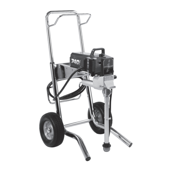
740
Airless Sprayer
800-120
800-121
800-122
800-123
Owner's Manual
For professional use only
i
NOTE: This manual contains important warnings
and instructions. Please read and retain for
reference.
© Titan Tool Inc. All Rights Reserved. Form No. 313-1695C
0808
•
Advertisement
Table of Contents

Related Manuals for Titan 740i


Summary of Contents for Titan 740i
- Page 1 High Rider Complete 800-121 NOTE: This manual contains important warnings and instructions. Please read and retain for Low Rider Bare 800-122 reference. Low Rider Complete 800-123 Printed in USA © Titan Tool Inc. All Rights Reserved. Form No. 313-1695C 0808 •...
-
Page 2: Safety Precautions
Do not use plastic drop cloths when blood stream. consultation with a plastic surgeon or spraying flammable materials. reconstructive hand surgeon may be advisable. • Use lowest possible pressure to flush equipment. • Do not spray onto pump assembly. © Titan Tool Inc. All rights reserved. - Page 3 • For electric units — Always unplug cord from outlet before working on equipment. • Do not use the hose as a strength member to pull or lift the equipment. • Do not lift by cart handle when loading or unloading. © Titan Tool Inc. All rights reserved.
-
Page 4: Table Of Contents
Safety Precautions section at the front of this container. manual before operating this equipment. 7. Turn the unit off by moving the ON/OFF switch to the OFF position. © Titan Tool Inc. All rights reserved. -
Page 5: Preparing To Paint
Solid Yellow = preparing for cleanup. Pressure priming pressure – 1800 PSI Indicator Solid Green = 1800 PSI – 3300 PSI Motor Running Indicator Programmer Port Programmer Port Dust Cover Circuit Breaker © Titan Tool Inc. All rights reserved. -
Page 6: Spraying
The cloth should be removed as soon as possible. orifice tip should be selected. Titan gun extensions are extremely helpful in these situations. Maintain uniform spray stroke action. Spray alternately from left to right and right to left. Begin movement of the gun before the Nearby objects such as automobiles, outdoor furniture, etc. -
Page 7: Cleanup
PULSE CLEAN position. Min. 4. If you have any further questions concerning your TITAN 7. Turn on the sprayer by moving the ON/ Airless Sprayer, call TITAN: OFF switch to the ON position. -
Page 8: Replacing The Filters
1. Loosen and remove the filter housing by hand. Electrostatic discharge (ESD) potential could cause damage to electronic control. use Titan ESD wrist 2. Slip the filter off of the filter support spring. strap P/N 700-1037 or equivalent when working on 3. -
Page 9: Replacing The Gears
Pump Block 19. Slide the motor shroud over the motor. Make sure the Mounting housing gasket is positioned properly. Screw 20. Secure the motor shroud with the four motor shroud screws. © Titan Tool Inc. All rights reserved. -
Page 10: Replacing The Prime/Spray Valve
Replace if they are worn or damaged. 9. Reassemble the valves by reversing the steps above. NOTE: During reassembly, make sure the o-ring between the pump block and foot valve housing is lubricated with grease and in position. © Titan Tool Inc. All rights reserved. - Page 11 NOTE: coat the piston guide tool and the piston rod with grease before inserting them into the pump block. 16. Place the piston insertion tool (included in the repacking kit) over the top of the piston rod. © Titan Tool Inc. All rights reserved.
-
Page 12: Troubleshooting
Faulty or loose wiring. Inspect or take to a Titan authorized service center. Excessive motor temperature. Allow motor to cool. ON/OFF switch is defective. - Page 13 Notes © Titan Tool Inc. All rights reserved.
-
Page 14: Français
Se servir de la pression la plus basse possible pour vidanger l’appareil. s’avérer nécessaire de consulter un plasticien ou un spécialiste en chirurgie reconstructive de la main. • Ne pas pulvériser de produit sur la pompe. Français © Titan Tool Inc. Tous droits réservés. - Page 15 électrique de la prise avant de travailler sur l’équipement. • N’utilisez pas le tuyau pour tirer ou soulever l’équipement. • Ne pas soulever par la poignée de chariot en chargeant ou en déchargeant. © Titan Tool Inc. Tous droits réservés. Français...
-
Page 16: Español
• Use la presión más baja posible para enjuagar el equipo. • No rocíe el ensamblaje de la bomba. Español © Titan Tool Inc. Todos los derechos reservados. - Page 17 • No utilice la manguera como elemento de fuerza para tirar del equipo o levantarlo. • No levantar por la manija del carro al cargar o descargando. © Titan Tool Inc. Todos los derechos reservados. Español...
-
Page 18: Parts Listings
Motor assembly (see separate listing) ..1 763-552 Lock washer ..........2 761-178 Screw ............4 710-033 Screw ............2 800-915 PRIME/SPRAY valve assembly ....1 704-304 Pail hook ...........1 702-239 Return hose (High Rider)......1 730-334 Hose clamp ..........1 © Titan Tool Inc. All rights reserved. -
Page 19: Motor Assembly
GREEN Assembly Ground Electronic WHITE Control Assy BLACK Motor Chassis BLACK Wire Assembly 765-072 NOTE: all electrical work should be Circuit performed by a Titan authorized Breaker service center. 765-327 Switch 780-380 WHITE © Titan Tool Inc. All rights reserved. -
Page 20: Gear Box Assembly
Gear Box assembly © Titan Tool Inc. All rights reserved. -
Page 21: High Rider Cart Assembly
Hex head screw ........4 800-469 Handle assembly 710-199 Plug ............2 (includes items 1, 3, 4, 12, 13, 18, and 19) ...1 800-593 Wheel ............2 704-354 Wheel spacer (not shown) ......4 335-018 Plug ............2 © Titan Tool Inc. All rights reserved. -
Page 22: Fluid Section Assembly
Viton o-ring (item 36) with optional PTFE o-ring (P/N 700-897). Install with o-ring tool (P/N 700-890). O-Ring Raised Lip Closer Install lower packing with the side that has the o-ring closest to the top of the packing facing up. © Titan Tool Inc. All rights reserved. -
Page 23: Suction Set Assembly, Low Rider
Return hose assembly ......1 704-121 O-ring ............2 704-109 O-ring (for hot solvents, optional) 700-1024 Elbow ............1 704-127 Retaining clip ..........1 700-1023 Siphon hose (includes items 2–4, and 7) ......1 755-135 Clip ............1 700-805 Inlet screen ..........1 © Titan Tool Inc. All rights reserved. -
Page 24: Accessories
Warranty Titan Tool, Inc., (“Titan”) warrants that at the time of delivery to the original purchaser for use (“End User”), the equipment covered by this warranty is free from defects in material and workmanship. With the exception of any special, limited, or extended warranty published by Titan, Titan’s obligation under this warranty is limited to replacing or repairing without charge those parts which, to Titan’s reasonable satisfaction, are shown to be defective within twelve (12) months after sale...
Need help?
Do you have a question about the 740i and is the answer not in the manual?
Questions and answers
I have a 740j that I bought from a neighbor and he say he don't remember the code ,any way to reset the code ?
To reset the code for a Titan 740i, you need to identify and fix the root cause of the issue first. For example, if the problem is related to the ABS module or speed sensor, those parts must be repaired or replaced. After fixing the issue, you can reset the code using a diagnostic tool like INPA or another OBD-II scanner that can clear fault codes. Simply clearing the code without fixing the problem will likely result in the code returning.
This answer is automatically generated