
Subscribe to Our Youtube Channel
Related Manuals for Titan Performance 750e


Summary of Contents for Titan Performance 750e
- Page 1 Operating manual Performance Series 750e Airless high-pressure spraying unit Performance Series 750e Edition 12 / 2009 0558 942B...
- Page 2 The operating instructions state that the following points must always be observed before starting up. Faulty units must not be used. Secure Titan spray gun using the safety catch on the trigger. 3. Ensure that the unit is properly earthed. The connection must take place through a correctly earthed two-pole and earth socket outlet.
-
Page 3: Table Of Contents
Contents Contents Page Page Safety regulations for Airless spraying ....... 4 Remedy in case of faults ..........13 Earthing instructions............5 Servicing ...............14 General view of application...........6 10.1 General servicing ............14 Application................6 10.2 High-pressure hose ............14 Coating materials .............6 Repairs at the unit ............14 Description of unit ............6 11.1 Relief valve..............14 Airless process ..............6... -
Page 4: Safety Regulations For Airless Spraying
Safety Regulations Safety regulations for Airless spraying This manual contains information that must be read and understood before using the equipment. When you come to an area that has one of the following symbols, pay particular attention and make certain to heed the safeguard. -
Page 5: Earthing Instructions
Safety regulations General view of application HAZARD: HAZARDOuS VAPORS HAZARD: EXPLOSION HAZARD DuE TO INCOMPATIBLE MATERIALS Paints, solvents, insecticides, and other materials can be harmful if inhaled or come in contact with Will cause severe injury or property damage. body. Vapors can cause severe nausea, fainting, or poisoning. -
Page 6: General View Of Application
In the following there is a short description of the technical construction for better understanding of the function. No other materials should be used for spraying without Titan’s approval. Titan Performance Series units are electrically driven high- pressure spraying units. A gear unit transfers the driving force to a crankshaft. The Filtering... -
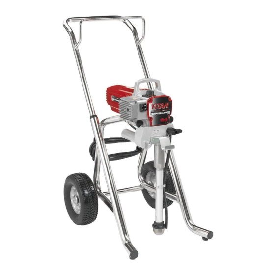
Page 7: Legend For Explanatory Diagram Performance Series 750E
Description of unit Legend for explanatory diagram Performance Series 750e 1 Spray gun 9 Pressure control knob 2 High-pressure hose 10 ON/OFF switch 3 Return hose 11 Circuit breaker 4 Suction hose 12 Pressure gauge 5 Frame 13 Oil cup for Piston Lube (Piston Lube prevents 6 Drip cup increased wear of the packings) 7 Power cord 14 Pail bracket (cart model only) -
Page 8: Technical Data
Description of unit Starting operation Starting operation Technical data Voltage: 110 Volt AC, 50/60 Hz High-pressure hose, spray gun and Max. current consumption: 12.5 A @ 110VAC separating oil Power cord: 3 x 1.5 mm – 6 m 1. Screw the pressure gauge (1) to the coating material Acceptance capacity: 950 Watt outlet (Fig. 3, Item 2). Max. operating pressure: 214 bar (21,4 MPa) 2. Screw the high-pressure hose (3) to the coating material outlet on the pressure gauge (Fig. 3, Item 4). -
Page 9: Pressure Control Knob Settings
Starting operation Pressure control knob settings (Fig. 5) 1. Yellow zone (Minimum Bar - 115 Bar) 2. Green zone (115 - 230 Bar) 3. Black zone (0 bar, no pressure generation) 4. Red zone (Pulse Clean) Min. PSI (Bar) Pulse Clean Max. PSI (Bar) Connection to the mains network The unit must be connected to an appropriately- grounded safety outlet. Attention Before connecting the unit to the mains supply, ensure that the Taking the unit into operation with coating... -
Page 10: Spraying Technique
High-pressure hose The unit is equipped with a high-pressure hose specially suited for piston pumps. 25 - 30 cm Only use Titan original-high-pressure hoses in order to ensure functionality, safety and durability. Interruption of work 1. Open the relief valve, valve position PRIME (k circulation). -
Page 11: Cleaning The Unit (Shutting Down)
Cleaning the unit (shutting down) Cleaning the unit (shutting down) Suction filter (stand model only) A clean state is the best method of ensuring operation without problems. After you have finished spraying, clean the unit. Under A clean suction filter always guarantees no circumstances may any remaining coating material dry and maximum feed quantity, constant spraying harden in the unit. -
Page 12: Cleaning Airless Spray Gun
Cleaning the unit (shutting down) Cleaning the Airless spray gun 1. Rinse Airless spray gun with an appropriate cleaning agent. 2. Clean tip thoroughly with appropriate cleaning agent so that no coating material residue remains. 3. Thoroughly clean the outside of the Airless spray gun. Intake filter in Airless spray gun 1. Pull the bottom of the trigger guard forward (1) so that it comes loose from the handle assembly (5). -
Page 13: Remedy In Case Of Faults
Piston is worn. Remove and replace piston. Increased pulsation at the spray Incorrect high-pressure hose type. Only use Titan original-high-pressure hoses in order to ensure functionality, safety and durability. Tip worn or too large. Replace tip. Pressure too high. -
Page 14: Servicing
General servicing remove the front cover. Servicing of the unit should be carried out once annually by the 2. Switch the unit ON and then OFF so that the piston rod is Titan service. positioned in the lower stroke position. 1. Check high-pressure hoses, device connecting line and plug for damage. Danger of crushing - do not reach with the 2. Check the inlet valve, outlet valve and filter for wear. -
Page 15: Packings
Repairs at the unit 11.3 Packings 1. Remove inlet valve housing in accordance with the steps in Chapter 11.2, Page 16. 2. It is not necessary to remove the outlet valve. 3. Unscrew both cylinder head screws (Fig. 12, Item 1) from the pump manifold (2) with a 3/8 inch hexagon socket head wrench. 4. Slide the pump manifold (2) and piston (3) forward until 8. Clean pump manifold (2). -
Page 16: Replacing The Motor Assembly
24. Install front cover. 11.4 Replacing the motor assembly Electrostatic discharge (ESD) potential could cause damage to electronic control. use Titan ESD wrist strap P/N 0507958 or equivalent when 11.5 Replacing the Gears working on electronic control with electronic cover removed. -
Page 17: Replacing The Transducer
Repairs at the unit 10. Remove and inspect the crankshaft/gear assembly (11) for Make sure the transducer is aligned properly damage or excessive wear. If damaged or worn, replace with the hole in the pump manifold during the crankshaft/gear assembly. reassembly. Improper alignment may cause 11. Reassemble the pump by reversing the above steps. damage to the transducer o-ring. -
Page 18: Performance Series 750E Connection Diagram
Repairs at the unit 11.7 Performance Series 750e connection diagram Performance Series 750e... -
Page 19: Accessories For Performance Series 750E
Accessories Appendix Accessories for Performance Series 750e Liquid Shield Plus Airless Tip Selection Cleans and protects spray systems against Tips are selected by the orifice size and fan width. The proper rust, corrosion and premature wear. Now with selection is determined by the fan width required for a specific -25º anti-freeze protection. job and by the orifice size that will supply the desired amount of fluid and accomplish proper atomization. Part # Description For light viscosity fluids, smaller orifice tips generally are desired. 314-483 4 ounce (112 ml) bottle For heavier viscosity materials, larger orifice tips are preferred. 314-482 1 liter bottle Please refer to the chart below. Piston Lube Do not exceed the sprayer’s recommended tip size. -
Page 20: Spare Parts List For Main Assembly
Spare parts list Performance Series 750e Main Assembly Performance Series 750e... - Page 21 Item Part No. Description Item Part No. Description 0558 302 Motor shroud 0558 377A Fluid section assembly (cart) 9805 287 Screw (4) 0558 376A Fluid section assembly 0508 775 Power cord (stand) 9800 340 Ground screw 700-252 Cam base 765-072 Jumper wire 700-759 Groove pin 800-461...
-
Page 22: Spare Parts List For Fluid Section
Spare parts list Performance Series 750e Fluid section Performance Series 750e... - Page 23 Item Part No. Description 705-104 Retainer 705-105 Piston guide ------- Upper packing 0551 681 Pump manifold 227-006 Fitting 800-925 Bypass valve assembly 700-537 Gasket ------- Lower packing 800-452 Piston rod 800-348 Seal 0294 516 Upper cage 0507 454 Washer 9841 502 Outlet valve ball 0294 516 Outlet valve seat 800-336...
-
Page 24: Spare Parts List For Drive Assembly
Spare parts list Performance Series 750e Drive Assembly Item Part No. Description 0558 356A Housing assembly 704-174 Thrust washer 704-173A Gear/crankshaft assembly 704-176 2nd stage gear 0551 599 Motor assembly (without electronic control assembly) 9820 213 Washer (4) 9800 341 Screw (4) 704-301A Slider assembly 0551 612 Electronic control assembly... -
Page 25: Spare Parts List For Upright Cart Assembly
Spare parts list Performance Series 750e upright cart assembly Item Part No. Description 0551 679 Handle assembly (includes items 2-3) 856-002 Washer (4) 856-921 Screw (2) 0507 774 Screw (4) 0507 655 Cord wrap (2) 0551 780 Cart weldment 0278 373 Wheel (2) 0294 534 Spacer (4) 9890 104 Axle cap (2) 0294 635 Plug (2) -
Page 26: Spare Parts List Of Frame
Spare parts list Performance Series 750e Stand Item Part No. Description 700-761 Cord holder 806-071 Leg, left 9885 546 Plug (2) 700-069 Screw 226-001 806-061 Leg, right 704-244 Tube clip 0551 434 Screw 700-1041 Drip cup 9805 230 Screw 9885 546 Plug (2) 0551 526 Left leg assembly... -
Page 27: Spare Parts List For Suction System
Spare parts list Performance Series 750e Suction system Item Part No. Description 0551 706 Siphon hose 9850 638 Tie wrap (2) 0551 707 Retun tube 0279 459 Clip 0551 705 Siphon tube assembly (includes items 1-4) Performance Series 750e... -
Page 28: Warranty
This warranty does not apply in the case of damage or wear caused by abrasion, corrosion or misuse, negligence, accident, faulty installation, substitution of non-Titan component parts, or tampering with the unit in a manner to impair normal operation. Defective parts are to be returned to an authorized Titan sales/service outlet. All transportation charges, including return to the factory, if necessary, are to be borne and prepaid by the End User. Repaired or replaced equipment will be returned to the End User...
Need help?
Do you have a question about the Performance 750e and is the answer not in the manual?
Questions and answers