Table of Contents
Advertisement
Quick Links
Download this manual
See also:
User Manual
Advertisement
Table of Contents

Related Manuals for D-Link DES-2108


Summary of Contents for D-Link DES-2108
- Page 1 DES-2108 8-port 10/100 Fast Ethernet Switch User’s Guide...
-
Page 2: Fcc Warning
FCC Warning This equipment has been tested and found to comply with the limits for a Class A digital device, pursuant to Part 15 of the FCC Rules. These limits are designed to provide reasonable protection against harmful interference when the equipment is operated in a commercial environment. -
Page 3: Table Of Contents
ABLE OF ONTENTS About This Guide ................1 Terms ................... 1 Overview of this User’s Guide ............ 1 Introduction..................2 Fast Ethernet Technology ............2 Switching Technology ..............2 Switch Description............... 3 Features..................4 Ports ..................... 5 Unpacking and Setup ................6 Unpacking.................. - Page 4 10/100M Fast Ethernet Ports Status LEDs ........ 12 Introduction To Switch Management ..........15 Management Options ..............15 Web Management Utility............15 Web-based Management Interface..........15 Command Line Interface (CLI) ..........16 SNMP-Based Management............16 Configuration The Switch..............17 Web Management Utility............17 Installing the Web Management Utility......
- Page 5 Static MAC ................ 40 IGMP Snooping Setting............. 42 Storm Control..............43 Device Status ..............44 Statistic................45 System Setting ..............46 Trap Setting................ 47 Set Password ..............48 Backup Setting ..............48 Reset Setting ..............49 System Reboot ..............49 Logout................
- Page 6 Spanning Tree Commands ..........84 SNMP Commands ............. 90 IGMP Snooping Commands ..........97 Static MAC Commands ........... 102 Technical Specifications ..............110 Warranty and Registration Information ........... 112...
-
Page 7: Terms
BOUT UIDE This user’s guide tells you how to install your DES-2108, how to connect it to your network. Terms For simplicity, this documentation uses the terms “Switch” (first letter upper case) to refer to the DES-2108, and “switch” (first letter lower case) to refer to all Ethernet switches, including the DES-2108. -
Page 8: Introduction
NTRODUCTION This section describes the features of the DES-2108, as well as giving some background information about Fast Ethernet and Switching technology. Fast Ethernet Technology The growing importance of LANs and the increasing complexity of desktop computing applications are fueling the need for high performance networks. -
Page 9: Switch Description
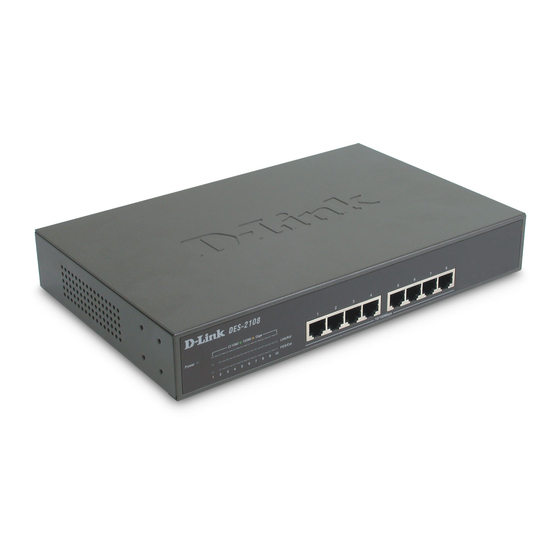
Switch Description The DES-2108 is equipped with unshielded twisted-pair (UTP) cable ports providing dedicated 10 or 100 Mbps bandwidth. The Switch has 8 UTP ports and Auto MDI-X/MDI-II convertible ports that can be used for up-linking to another switch. -
Page 10: Features
Management engine can be configure the Switch's settings for priority queuing, VLANs, and port monitoring, and port speed. Features The DES-2108 was designed for easy installation and high performance in an environment where traffic on the network and the number of users increase continuously. -
Page 11: Ports
Supports a packet buffer of up to 256 Kbytes. IGMP Snooping support. SNMP support. Port Mirror support. MIB support for: RFC1213 MIB II. Private MIB. Provides parallel LED display for port status such as link/act, speed, etc. Ports Eight (8) 10/100Mbps 100BASE-TX (Auto MDI-X/MDI-II) ports for connecting to end stations, servers, hubs and other networking devices. -
Page 12: Unpacking And Setup
Unpacking Open the shipping carton of the Switch and carefully unpack its contents. The carton should contain the following items: One DES-2108 Fast Ethernet Switch Four rubber feet with adhesive backing One AC power cord Mounting kit (two brackets and screws) CD-ROM (This User’s Guide and Utility) -
Page 13: Installing The Switch On A Desktop
Install the Switch in a fairly cool and dry place for the acceptable temperature and humidity operating ranges. Install the Switch in a site free from strong electromagnetic field generators (such as motors), vibration, dust, and direct exposure to sunlight. When installing the Switch on a level surface, attach the rubber feet to the bottom of the device. -
Page 14: Installing The Switch On A Rack
Installing the Switch on a Rack The Switch can be mounted in a standard 19" rack. Use the following diagrams to guide you. Figure 2. Fasten mounting brackets to Switch Fasten the mounting brackets to the Switch using the screws provided. With the brackets attached securely, you can mount the Switch in a standard rack as shown in Figure 2-2 on the following page. -
Page 15: Power On
Power on The DES-2108 can be used with AC power sources 100 - 240 VAC, 50 - 60 Hz. The Switch’s power supply will adjust to the local power source automatically. Plug one end of the AC power cord into the power connector of the Switch and the other end into the local power source outlet. -
Page 16: Identifying External Components
DENTIFYING XTERNAL OMPONENTS This chapter describes the front panel, rear panel and LED indicators of the Switch Front Panel Components The front panel of the Switch consists of eight (8) 10/100Mbps Fast Ethernet ports, LED indicators and Reset button. Figure 4. Front panel view RJ-45: Eight 10/100Mbps Fast Ethernet ports. -
Page 17: Rear Panel
Rear Panel The rear panel of the Switch contains an AC power connector. Figure 5. Rear panel view The AC power connector is a standard three-pronged connector that supports the power cord. Plug-in the female connector of the provided power cord into this socket, and the male side of the cord into a power outlet. -
Page 18: Power And Cpu Leds
Power and CPU LEDs Power : This LED will light green after the Switch is powered on to indicate the ready state of the device. : When the switch powered off or the power cord has improper connection. : When the CPU is working, the CPU LED is blinking. Blinking On/Off : The CPU is not working. -
Page 19: Introduction To Switch Management
NTRODUCTION WITCH ANAGEMENT Management Options Web Management Utility Web-based Management Interface Command Line Interface (CLI) SNMP-Based Management Managing Management Options This system may be managed in-band using TCP/IP Telnet protocol and web-based management, accessible through a web browser. Web Management Utility With the Web Management Utility, you can easily discover all the Web Management Switch, assign the IP Address, changing the password and upgrading the new firmware. -
Page 20: Command Line Interface (Cli)
Command Line Interface (CLI) The Switch supports a Command Line Interface (CLI) that allows the user to connect to the Switch’s management agent using the TCP/IP Telnet protocol. SNMP-Based Management You can manage the Switch with an SNMP-compatible console program. The Switch supports SNMP version 1.0. The SNMP agent decodes the incoming SNMP messages and responds to requests with MIB objects stored in the database. -
Page 21: Configuration The Switch
ONFIGURATION WITCH Through the Web Browser, Telnet and SNMP you can configure the Switch such as Port setting, VLAN, QoS, SNMP, Spanning Tree… etc. Web Management Utility With the attached Web Management Utility, you can easily discover all the Web Management Switch, assign the IP Address, changing the password and upgrading the new firmware. - Page 22 Figure 7. Web Management Utility The Web Management Utility was divided into four parts, Discovery List, Monitor List, Device Setting and Toolbar function, for details instruction, follow the below section.
-
Page 23: Discovery List
Discovery List This is the list where you can discover all the Web management devices in the entire network. By pressing the “Discovery” button, you can list all the Web Management devices in the discovery list. Double click or press the “Add to monitor list” button to select a device from the Discovery List to the Monitor List. - Page 24 System Name: Shows the appointed device system name. Location: Shows where the device is located. Trap IP: Shows the IP where the Trap to be sent. Subnet Mask: Shows the Subnet Mask set of the device. Gateway: Shows the Gateway set of the device. View Trap: The Trap function can receive the events that happen from the Web Management Switch in the Monitor List.
-
Page 25: Device Setting
In factory default, the IP address of the DES-2108 will atomically assign from DHCP server (DHCP enabled). If your network has no DHCP server, the DES-2108 will fail to get IP address, and the IP address of DES-2108 will be assigned to default IP address of 192.168.0.1 and netmask is 255.255.255.0. -
Page 26: Firmware Upgrade
Figure 10. Configuration Setting Password Change: You can use this Password Change when you need to change the password, fill in the password needed in the dialog box and press “Set” button to precede the password change immediately. Figure 11. Password Change Firmware Upgrade: When the device has a new function, there will be a new firmware to update the device, use this function to update. -
Page 27: Toolbar
Toolbar The toolbar in the Web Management Utility have four main tabs, File, View, Options and Help. File TAB: In the “File TAB”, there are Monitor Save, Monitor Save As, Monitor Load and Exit: Monitor Save: To record the setting of the Monitor List to the default, when you open the Web Management Utility next time, it will auto load the default recorded setting. -
Page 28: Configuring The Switch Using Web Browser
Configuring the Switch using Web Browser All software functions of the DES-2108 can be managed, configured and monitored via the embedded web-based (HTML) interface. The Switch can be managed from remote stations anywhere on the network through a standard browser such as Netscape Navigator or Microsoft Internet Explorer. -
Page 29: Login To Web Manager
Login to Web Manager Before you configure this device, note that when the Web Smart Switch is configured through an Ethernet connection, make sure the manager PC must be set on same the IP network. For example, when the default IP address of the Web Smart Switch is 192.168.0.1, then the manager PC should be set at 192.168.0.x (where x is a number between 2 and 254), and the default subnet mask is 255.255.255.0. - Page 30 After entering the password, the main page comes up, the screen will display the device status. Figure 15. Device Status...
-
Page 31: Setup Menu
Setup Menu When the main page appears, find the Setup menu in the left side of the screen (Figure 16). Click on the setup item that you want to configure. There are fifteen options: Port Settings, VLAN Settings, Mirror Setting, Spanning Tree Settings, SNMP Settings, Static MAC Settings, IGMP Snooping Settings, Strom Control Settings, Device Status, Statistic, System Settings, Trap Setting, Password Setting, Backup Setting, Reset Setting and System Reboot Setting as shown in... -
Page 32: Configuring Setup Setting
Configuring Setup Setting Find that there are four items, including Port Settings, VLAN Settings, Mirror Settings, Spanning Tree, SNMP, Static MAC and IGMP Snooping in Setup menu. Port Settings In Port Settings menu (Figure 17), this page will show each port’s status, press the ID parameter to set each port’s Speed, Flow Control, QoS priority and Link Status. -
Page 33: Vlan Settings (Virtual Local Area Network)
VLAN Settings (Virtual Local Area Network) The DES-2108 supports two of VLAN type: Port-Based VLAM or IEEE 802.1Q-Based VLAN. The VLAN setting only working on one of the two VLAN types, the default VLAN setting is Port-Based VLAN type, if you change to the other VLAN mode, the current VLAN setting will be erased. - Page 34 Port-based VLAN: To add a VLAN group, press “Add Group” button, the new VLAN configuration window will pop out, you can fill in the description in order to describe this VLAN Group, check on the port to be a member to this VLAN Group, and press “Apply”...
- Page 35 IEEE 802.1Q VLAN: VID Table Setting: select the VID group that you set. When you select VID Table Setting, press “Add new VID” to create new VID group, from port 01 ~ port 48, select Untag Port, Tag Port or Not Member for each port.
-
Page 36: Mirror Setting
Figure 24. Mirror Setting Port Mirroring is a method of monitoring network traffic that forwards a copy of each incoming and/or outgoing packet from one port of a network switch to another port where the packet can be studied. It enables the manager to keep close track of switch performance and alter it if necessary. -
Page 37: Spanning Tree Setting
Figure 25. Mirror Setting Spanning Tree Setting This Switch supports the 802.1d Spanning Tree Protocol. Every segment will have a single path to the root bridge. All bridges listen for BPDU packets. However, BPDU packets are sent more frequently - with every Hello packet. BPDU packets are sent even if a BPDU packet was not received. - Page 38 STP Function: To selecting enable or disable STP function on the Switch. Bridge Priority: This value between 0 and 65535 to specify the priority for forwarding packets. The lower the value, the higher the priority. The default is 32768. Bridge Max Age: This value may be set to ensure that old information does not endlessly circulate through redundant paths in the network, preventing the effective propagation of the new information.
-
Page 39: Snmp Setting
MIB specifications and the protocol used to access this information over the network. The DES-2108 supports the SNMP versions 1. In SNMP v.1, user authentication is accomplished using 'community strings', which function like passwords. The remote user SNMP application and the Switch SNMP must use the same community string. - Page 40 Traps Traps are messages that alert network personnel of events that occur on the Switch. The events can be as serious as a reboot (someone accidentally turned OFF the Switch), or less serious like a port status change. The Switch generates traps and sends them to the trap recipient (or network manager).
- Page 41 Add Group: To add a SNMP Community group, press “Add Group” button, the Add SNMP Community configuration window will pop out; fill in the community name and assign the community enable read_only or read_write. Press “Apply” button to execute the setting. Figure 28.
- Page 42 Modify Group: To modify previously defined SNMP Community group, click on the ID parameter to enter to the selected SNMP Community Group to configure its community name and community enable. Press “Apply” to save change of the SNMP Community Group. Figure 30.
- Page 43 Add Trap: To create a recipient of SNMP traps generated by the Switch’s SNMP agent, press “Add Trap” button, and the SNMP Trap Set window will pop out; you can fill in the community name and trap IP address of the remote management station that will serve as the SNMP host for the Switch and checked the events selection to enabled selected event traps.
-
Page 44: Static Mac
Modify Trap: To modify previously defined SNMP Trap, click on the ID parameter to enter to the selected SNMP Trap to configure its community name, IP address and events. Press “Apply” to save change of the SNMP Trap. Figure 34. Modify SNMP Trap Static MAC The Static MAC function allows you to enable the Switch to forward the data packets to specific MAC address and specific port. - Page 45 Disable auto learning excluding uplink port: When enable the Static MAC function, the Switch’s auto learning function will be disable, check the dialog box of the “Disable auto learning excluding uplink port” and then check the dialog box of port numbers to enable the auto learning function of the port, and the Switch will forward data following the Static MAC Address Table and the Switch’s auto learn MAC address table to the specific port.
-
Page 46: Igmp Snooping Setting
Figure 37. Delete Static MAC IGMP Snooping Setting IGMP Snooping allows the Switch to read the Multicast Group IP address and the corresponding MAC address from IGMP packets that pass through the Switch. The number of IGMP reports that were snooped is displayed in the Reports field. -
Page 47: Storm Control
Host Timeout (1-16711450): Specifies the maximum amount of time a host can be a member of a multicast group without the Switch receiving a host membership report. The default is 260 seconds. Router Timeout (1-16711450): Specifies the maximum amount of time a route can be a member of a multicast group without the Switch receiving a host membership report. -
Page 48: Device Status
Device Status Click on the “Status” to present the device status on this screen, it will show the System Status, Port Status, VLAN Setting, Mirror Setting, Spanning Tree status, SNMP Setting and IGMP Setting. Figure 40. Device Status. Press “Refresh” when you need to renew the posted information. -
Page 49: Statistic
Statistic The Statistic Menu screen will show the status of each port packet count. Figure 41. Device Statistics For Detail packet information, click on the ID parameter as Figure 42. Figure 42. Port Statistics... -
Page 50: System Setting
System Setting The System Setting includes the System name, Location name, Login Timeout, IP Address, Subnet Mask and Gateway. Through the Web Management Utility, you can easily recognize the device by using the System Name and the Location Name. The Login Timeout is to set the idle time-out for security issue, when there is no action when running the Web Smart Utility and the time is up, you must re-login to Web Smart Utility before you set the Utility. -
Page 51: Trap Setting
Trap Setting The Trap Setting enables the device to monitor the Trap through the Web Management Utility, set the Trap IP Address of the manager where the trap to be sent. Figure 44. Trap Setting System Events: Monitoring the system’s trap. Device Bootup: a trap when booting up the system. -
Page 52: Set Password
Set Password Password is the invaluable tool for the manager to secure Web Management Switch, use this function to change the password. If you forget the password, press the “Reset” button in the rear panel of the Switch, the current setting includes VLAN, Port Setting… etc. will be lost and the Switch will restore to the default setting. -
Page 53: Reset Setting
Note: when restoring a recorded file, the current password will not be erased. Reset Setting The Factory Reset button helps you to reset the device back to the default setting from the factory. Be aware that the entire configuration will be reset, the IP address of the device will be get from DHCP server (factory default is DHCP enabled) or got the default IP address of 192.168.0.1 when fail to get the IP address from DHCP server. -
Page 54: Logout
Logout When press this function, the web configuration will go back to first Login page. Figure 49. Logout... -
Page 55: Configuring The Switch Using The Cli
Configuring the Switch using the CLI The Switch can be managed through the TCP/IP Telnet protocol. The Command Line Interface (CLI) can be used to configure and manage the Switch via TCP/IP Telnet protocol. This section provides a reference for all of the commands contained in the CLI. -
Page 56: Using The Cli Via Telnet Interface
Where ip-address is the IP address you have assigned to the Switch. When you telnet to the Switch, it displays its login-in message: Figure 51. The DES-2108 console login At this point you can enter the password you have assigned to your print server. -
Page 57: Command Syntax
Command Syntax The following symbols are used to describe how command entries are made and values and arguments are specified in this manual. The online help contained in the CLI and available through console interface uses the same syntax. Note: All commands are case sensitive. Be sure to disable Caps Lock or any other unwanted function that changes text case. - Page 58 | vertical bar Separates two or more mutually exclusive items Purpose in a list, one of which must be entered. Syntax show snmp [community | host] In the above syntax sample, you must specify Description either a community or host configuration to be show.
-
Page 59: Basic Switch Commands
Basic Switch Commands The basic switch commands in the Command Line Interface (CLI) are listed (along with the appropriate parameters) in the following table. Command Parameters show switch <system_contact 20> config snmp system_contact config snmp <system_name 20> system_name <location_name 20> config snmp system_location <value 1 -1048575>... - Page 60 Example usage: To display the Switch’s information: Figure 53. show switch command config snmp system_contact Used to enter the name of a contact person who Purpose is responsible for the Switch. Syntax config snmp system_contact <system_contact> The config snmp system_contact command is Description used to enter the name and/or other information to identify a contact person who is responsible...
- Page 61 Example usage: To configure the Switch contact to “Eddy_Chou”: Figure 54. config snmp system_contact command config snmp system_name Used to configure the name for the Switch. Purpose Syntax config snmp system_name <system_name> Description config snmp system_name command configures the name of the Switch. Parameters <system_name>...
- Page 62 config snmp system_location Used to enter a description of location of the Purpose Switch. Syntax config snmp system_location <system_location> The command is used to enter a description of Description the location of the Switch. Parameters <system_location> maximum character can be used, space character is not allowed.
- Page 63 config snmp aging_time Used to set the aging time of the forwarding Purpose database. Syntax config snmp system aging_time <value 1 - 1048575 sec> The aging time affects the learning process of Description the Switch. Dynamic forwarding table entries, which are made up of the source MAC addresses and their associated port numbers, are deleted from the table if they are not accessed within the aging time.
- Page 64 Example usage: To set the aging time: Figure 57. config snmp aging_time command reset Purpose Used to reset the Switch to the factory default setting Syntax reset <config> The command is used to restore the Switch’s Description configuration to the default setting assigned from the factory.
- Page 65 logout Used to log out a user from the Switch’s console. Purpose Syntax logout This command terminates the current session on Description the Switch’s console. Parameters None. Example usage: To terminate the current telnet console session: Figure 59. logout command save Used save...
-
Page 66: Basic Ip Commands
Example usage: To save the Switch’s current configuration to non-volatile RAM: Figure 60. save command Basic IP Commands The basic IP commands in the Command Line Interface (CLI) are listed (along with the appropriate parameters) in the following table. Command Parameters config ipif [ipaddress <network address>... - Page 67 Each command is listed, in detail, in the following sections. config ipif Used to configure the System IP interface. Purpose Syntax config ipif [ipaddress <network address> | {gw <ipaddress>} | dhcp {vid <vlan_id>}] This command is used to configure the System Description IP interface on the Switch.
-
Page 68: Switch Port Commands
show ipif Used to display the configuration of an IP Purpose interface on the Switch. Syntax show ipif This command will display the configuration of an Description IP interface of the Switch. Parameters None. Example usage: To display IP interface settings: Figure 62. - Page 69 Each command is listed, in detail, in the following sections. config ports Used to configure the Switch’s Ethernet port Purpose settings. Syntax [<portlist | all> {speed [disable |auto |10_half | 10_full | 100_half | 100_full | 1000_full} | {flow_control [enable | disable] | qos {normal | high]} This command allows for the configuration of the Description...
- Page 70 Example usage: To configure the speed of port 1-3 to be 100 Mbps, half duplex, disable of port 4-5, QoS of port 3, 4, 6 to be high priority and disable flow control of port 1, 2, 4, 6: Figure 63. config ports command show ports Used to display current configuration of a range of Purpose...
-
Page 71: Vlan Commands
Example usage: To display the configuration of all ports on the switch: Figure 64. show ports command VLAN Commands The VLAN commands in the Command Line Interface (CLI) are listed (along with the appropriate parameters) in the following table. Command Parameters [<vlan_name 8>... - Page 72 Command Parameters disable 802.1q_based vlan <portlist> <vlanid 1~4094> priority config pvid <0-7> disable port_based vlan enable 802.1q_based vlan Each command is listed, in detail, in the following sections. create vlan Used to create a VLAN on the Switch. Purpose Syntax create vlan [<vlan_name 8>...
- Page 73 To create an 802.1Q_based VLAN, tag 2: Figure 66. create vlan command (802.1q_based VLAN) delete vlan Used to delete a previously configured VLAN on the Purpose Switch. Syntax delete vlan [<vlan_name 8> | tag <vlanid 1~4094>] This command will delete a previously configured VLAN Description on the Switch Parameters...
- Page 74 To delete an 802.1Q_based VLAN, tag 10: Figure 68. delete vlan command (802.1q_based VLAN) config vlan Purpose Used additional ports previously configured VLAN. Syntax config vlan [<vlan_name 8> | tag <vlanid 1~4094> add {tagged | untagged} | delete <portlist>] Description This command allows you to add ports to the port list of previously configured VLAN.
- Page 75 Example usage: To add port 1, 3, 5, 6 to the “sales” VLAN group: Figure 69. config vlan command, add VLAN group members (port_based VLAN) To delete 4 through 6 ports from the “sales” VLAN group: Figure 70. config vlan command, delete VLAN group members (port_based VLAN) To add 1 through 3 as tagged ports to the VLAN tag 10: Figure 71.
- Page 76 To delete port 3 from the VLAN tag 10: Figure 72. config vlan command, delete VLAN group members (802.1q_based VLAN) config management _vlan Used to change the management VLAN in Purpose 802.1Q_based VLAN type on the Switch. Syntax config management _vlan This command allows...
- Page 77 enable port_based vlan Purpose Used to change the VLAN type to Port_based VLAN type on the Switch. Syntax enable port_based vlan Description This command allows you to change the VLAN type to Port_based VLAN on the Switch. None. Parameters Example usage: To switched the VLAN type to Port_based VLAN Figure 74.
- Page 78 enable 802.1q_based vlan Purpose Used to change the VLAN type to 802.1Q_based VLAN on the Switch. Syntax enable 802.1q_based vlan Description This command allows you to change the VLAN type to 802.1Q_based VLAN on the Switch. None. Parameters Example usage: To switched the VLAN type to 802.1Q_based VLAN Figure 76.
-
Page 79: Port Mirroring Commands
config pvid Used to configure the 802.1Q Port VLAN ID and priority. Purpose Syntax config pvid <portlist> <vlanid 1~4094> priority <0~7> Description This command allows you to configure the 802.1Q Port VLAN ID and priority. Parameters <portlist> - A port or range of ports to configure to the specified PVID. - Page 80 show mirror Each command is listed, in detail, in the following sections. config mirror port Used to configure a mirror port – source port pair Purpose on the Switch. Traffic for any source port to a target port can be mirrored for real-time analysis. Syntax [enable | disable] {<port>...
- Page 81 Example usage: To enable and configure the Port Mirror function of the Switch: Figure 79. config mirror port command To disable Port Mirror function of the Switch: Figure 80. config mirror port command, disable port mirror function show mirror Purpose Used to show the current mirroring configuration on the Switch.
-
Page 82: Trap Commands
Example usage: To display port mirroring configuration: Figure 81. show mirror command Trap Commands The trap mirroring commands in the Command Line Interface (CLI) are listed (along with the appropriate parameters) in the following table. Command Parameters ipaddress <ip_address> {vid config discovery <vlan_id>} trap_ip... - Page 83 Each command is listed, in detail, in the following sections. config discovery trap_ip Used to configure an IP address of the trap Purpose recipient of Web Management Utility to the Switch. Syntax config discovery trap_ip ipaddress <ip_address> {vid <vlan_id>} The command is configure an IP address of the Description trap recipient of Web Management Utility to the Switch.
- Page 84 config discovery trap_event Used to configure the events of the trap on the Purpose Switch. Syntax config discovery trap_event {[bootup | illegal_login | t_rx_err | t_tx_err | f_rx_err | f_tx_err | f_link_change]} The command is configure the events of the trap Description on the Switch..
- Page 85 Example usage: To configure the events type of the Switch: Figure 83. config discovery trap_event command...
- Page 86 delete discovery trap_event Purpose Used to delete previously configured events of trap on the Switch. Syntax delete discovery trap_event {[bootup | illegal_login | t_rx_err | t_tx_err | f_rx_rtt | f_tx_err | f_link_change]} The command is delete previously configured Description events of trap on the Switch. Parameters bootup - Disable the Switch’s boot up event.
- Page 87 show discovery trap Purpose Used to show the configuration of the discovery trap on the Switch. Syntax show discovery trap Description The command is display the configuration of the discovery trap on the Switch.. None. Parameters Example usage: To display discovery trap configuration: Figure 85.
-
Page 88: Spanning Tree Commands
Spanning Tree Commands The spanning tree commands in the Command Line Interface (CLI) are listed (along with the appropriate parameters) in the following table. Command Parameters enable stp disable stp {maxage <value 6-40> | hellotime <value config stp 1-10> | forwarddelay <4-30> | priority <value 1-65535>... - Page 89 disable stp Purpose Used to disable STP on the Switch. Syntax disable stp Description This command allows the Spanning Tree Protocol to be disabled on the Switch. None. Parameters Example usage: To disable STP on the Switch: Figure 87. disable stp command...
- Page 90 config stp Used to setup STP on the Switch. Purpose Syntax config stp {maxage <value 6-40> | hellotime <value 1-10> | forwarddelay <4-30> | priority <value 1-65535> | fbpdu [enable | disable]} This command is used to setup the Spanning Description Tree Protocol (STP) for the entire Switch.
- Page 91 higher the priority. The default is 32768. fbpdu [enable | disable] - Allows the forwarding of STP BPDU packets from other network devices when STP is disabled on the Switch. The default is enable. Example usage: To configure STP with maxage 40 and hellotime of 5 seconds: Figure 88.
- Page 92 Example usage: To configure STP with path cost 10, priority of 100 for ports 1-5: Figure 89. config stp ports command show stp Used to display the Switch’s current STP Purpose configuration. Syntax show stp This command displays the Switch’s current STP Description configuration.
- Page 93 show stp ports Purpose Used to display the Switch’s current STP group of ports configuration on the Switch. Syntax show stp ports {portlist} Description This command displays the STP group of configuration on the Switch. Parameters <portlist> - Specifies a port or range of ports to be viewed.
-
Page 94: Snmp Commands
SNMP Commands The SNMP commands in the Command Line Interface (CLI) are listed (along with the appropriate parameters) in the following table. Command Parameters create snmp <community_string 20> [read_only | read_write] community <community_string 20> [read_only | delete snmp read_write] community show snmp create snmp host <ipaddress>... - Page 95 Each command is listed, in detail, in the following sections. create snmp community Purpose Used to create an SNMP community string to define the relationship between the SNMP manager and an agent. The community string acts like a password to permit access to the agent on the Switch.
- Page 96 Example usage: To create the SNMP community string “admin”: Figure 92. create snmp community command delete snmp community Used to remove a specific SNMP community Purpose string from the Switch. Syntax delete snmp community <community_string 20> [ read_only | read_write ] This command is used to remove a previously Description defined SNMP community string from the Switch.
- Page 97 Example usage: To delete the SNMP community string “admin”: Figure 93. delete snmp community command show snmp community Used to display SNMP community strings Purpose configured on the Switch. Syntax show snmp community Description This command is used to display SNMP community strings that are configured on the Switch.
- Page 98 create snmp host Purpose Used to create a recipient of SNMP traps generated by the Switch’s SNMP agent. Syntax create snmp host <ipaddress> {vid <vlan_id>} trap_community <community_string> This command creates a recipient of SNMP traps Description generated by the Switch’s SNMP agent Parameters <ipaddress>...
- Page 99 Used to display the recipient of SNMP traps Purpose generated by the Switch’s SNMP agent. Syntax show snmp host This command is used to display the IP Description addresses and configuration information of remote SNMP managers that are designated as recipients of SNMP traps that are generated by the Switch’s SNMP agent.
- Page 100 Example usage: To enable SNMP trap support on the Switch: Figure 97. enable snmp traps command disable snmp traps Used to disable SNMP trap support on the Purpose Switch. Syntax disable snmp traps Description This command is used to disable SNMP trap support on the Switch.
-
Page 101: Igmp Snooping Commands
IGMP Snooping Commands The IGMP Snooping commands in the Command Line Interface (CLI) are listed (along with the appropriate parameters) in the following table. Command Parameters config router_ports [add | delete] <portlist> enable igmp snooping {forward_mcrouter_only} disable igmp snooping show router ports show igmp_snooping group [host_timeout <sec 1-16711450>... - Page 102 Example usage: To set up static router ports: Figure 99. config router_ports command (add static router ports) To delete static router ports: Figure 100. config router_ports command (delete static router ports) enable igmp snooping Purpose Used to enable IGMP snooping on the Switch. Syntax enable igmp snooping {forward_mcrouter_only} Description...
- Page 103 Example usage: To enable IGMP snooping on the Switch: Figure 101. enable igmp snooping command disable igmp snooping Used to disable IGMP snooping on the Switch. Purpose Syntax disable igmp snooping Description This command disables IGMP snooping on the Switch. None.
- Page 104 show router_ports Purpose Used to display the currently configured router ports on the Switch. Syntax show router_ports Description This command is used to display the currently configured router ports on the Switch. None. Parameters Example usage: To display the router ports: Figure 103.
- Page 105 Example usage: To view the current IGMP snooping group: Figure 104. show igmp_snooping command config igmp_snooping Used to configure IGMP snooping on the Switch. Purpose Syntax config igmp_snooping [host_timeout <sec 1- 16711450> | router_timeout <sec 1- 16711450>] This command allows you to configure IGMP Description snooping on the Switch.
-
Page 106: Static Mac Commands
Example usage: To configure IGMP snooping: Figure 105. config igmp_snooping command Static MAC Commands The layer 2 forwarding database commands in the Command Line Interface (CLI) are listed (along with the appropriate parameters) in the following table. Command Parameters enable smac disable smac [enable | disable exclude <portlist>] config auto_learning... - Page 107 enable smac Purpose Used to enable Static MAC function on the Switch. Syntax enable smac Description This command allows you to enable Static MAC function on the Switch. None. Parameters Example usage: Figure 106. enable Static MAC function disable smac Used to disable Static MAC function on the Purpose Switch.
- Page 108 config auto_learning Purpose Used to enables or disables the MAC address learning on the specified range of ports. Syntax config auto_learning [enable | disable exclude <portlist>] This command allows you to enables or disables Description the MAC address learning on the specified range of ports.
- Page 109 show smac Used to display the Static MAC address Purpose forwarding database. Syntax show smac This command allows you to display the Static Description MAC address forwarding database. Parameters None. Example usage: Figure 110. show Static MAC address forwarding database show fdb Used to display the dynamic MAC address Purpose...
- Page 110 Example usage: Figure 111. show Dynamic MAC address forwarding database create smac (port-based VLAN)
- Page 111 Used to create a static entry to the unicast MAC Purpose address forwarding table (database). Syntax create smac [mac <macaddress> port <port no.> | idx <mac address index list on fdb>] Description This command allows you to designate a range of ports as being connected to multicast-enabled routers.
- Page 112 Step1: show the DYNAMIC MAC SEARCH LIST Figure 113. show the DYNAMIC MAC SEARCH LIST Step2: create Static MAC from DYNAMIC MAC SEARCH LIST: Figure 114. create Static MAC from DYNAMIC MAC SEARCH LIST ID 001...
- Page 113 create smac (802.1Q VLAN) Used to create a static entry to the unicast MAC Purpose address forwarding table (database). Syntax [mac <macaddress> port <port no.> vid <vid> | idx <mac address index list on fdb>] This command allows you to designate a range Description of ports as being connected to multicast-enabled routers.
-
Page 114: Technical Specifications
ECHNICAL PECIFICATIONS General IEEE 802.3 10BASE-T Ethernet IEEE 802.3u 100BASE-TX Fast Ethernet Standards: ANSI/IEEE 802.3 Auto-negotiation IEEE 802.3x Full duplex Flow Control CSMA/CD Protocol: Data Ethernet: 10Mbps (half-duplex), 20Mbps (full-duplex) Transfer Fast Ethernet: 100Mbps (half-duplex), 200Mbps (full-duplex) Rate: Topology Star Ethernet: 2-pair UTP Cat. - Page 115 Physical and Environmental 100-240 VAC, 50-60 Hz AC inputs: Power Consumption: 9 watts maximum Operating 0 ~ 40 degrees Celsius Temperature: Storage Temperature: -10 ~ 70 degree Celsius Humidity: 10% ~ 90% RH, non-condensing Dimensions: 280 mm x 180 mm x 44 mm FCC Class A, CE Mark Class A, VCCI Class A EMI: Performance...
-
Page 116: Warranty And Registration Information
A R R A N T Y A N D E G I S T R A T I O N N F O R M A T I O N (All countries and regions excluding USA) Wichtige Sicherheitshinweise Bitte lesen Sie sich diese Hinweise sorgfältig durch. Heben Sie diese Anleitung für den spätern Gebrauch auf. - Page 117 Für einen Nennstrom bis 6A und einem Gerätegewicht grőßer 3kg ist eine Leitung nicht leichter als H05VV-F, 3G, 0.75mm2 einzusetzen. WARRANTIES EXCLUSIVE IF THE D-LINK PRODUCT DOES NOT OPERATE AS WARRANTED ABOVE, THE CUSTOMER'S SOLE REMEDY SHALL BE, AT D-LINK'S OPTION, REPAIR OR REPLACEMENT. THE FOREGOING WARRANTIES AND...
- Page 118 Limited Warranty Hardware: D-Link warrants each of its hardware products to be free from defects in workmanship and materials under normal use and service for a period commencing on the date of purchase from D-Link or its Authorized Reseller and extending for the length of time stipulated by the Authorized Reseller or D-Link Branch Office nearest to the place of purchase.
- Page 119 This Warranty applies on the condition that the product Registration Card is filled out and returned to a D-Link office within ninety (90) days of purchase. A list of D-Link offices is provided at the back of this manual, together with a copy of the Registration Card.
- Page 120 Registration Card. If a Registration Card for the product in question has not been returned to a D-Link office, then a proof of purchase (such as a copy of the dated purchase invoice) must be provided when requesting warranty service.
Need help?
Do you have a question about the DES-2108 and is the answer not in the manual?
Questions and answers