Table of Contents
Advertisement
Quick Links
Advertisement
Table of Contents

Related Manuals for Asus Z170-P D3


Summary of Contents for Asus Z170-P D3
- Page 1 Z170-P D3...
- Page 2 Product warranty or service will not be extended if: (1) the product is repaired, modified or altered, unless such repair, modification of alteration is authorized in writing by ASUS; or (2) the serial number of the product is defaced or missing.
-
Page 3: Table Of Contents
Contents Safety information ..................iv About this guide ..................iv Package contents ..................vi Z170-P D3 specifications summary ............vi Chapter 1: Product introduction Before you proceed ..............1-1 Motherboard overview ..............1-1 Central Processing Unit (CPU) ........... 1-3 System memory ................1-7 Expansion slots ................ -
Page 4: Safety Information
Safety information Electrical safety • To prevent electrical shock hazard, disconnect the power cable from the electrical outlet before relocating the system. • When adding or removing devices to or from the system, ensure that the power cables for the devices are unplugged before the signal cables are connected. If possible, disconnect all power cables from the existing system before you add a device. -
Page 5: Conventions Used In This Guide
Refer to the following sources for additional information and for product and software updates. ASUS websites The ASUS website provides updated information on ASUS hardware and software products. Refer to the ASUS contact information. Optional documentation Your product package may include optional documentation, such as warranty flyers, that may have been added by your dealer. -
Page 6: Package Contents
Turbo Boost Technology 2.0* ® * The Intel Turbo Boost Technology 2.0 support depends on the CPU types. ® ** Refer to www.asus.com for Intel® CPU support list. Intel Z170 Express Chipset Chipset ® 4 x DIMM, maximum 64GB, DDR3 3100(O.C)*/2933 (O.C.)*/2800(O.C.)*/ 2666(O. - Page 7 - 6 x USB 2.0/1.1 ports (4 ports at mid-board, 2 ports at the rear panel) ASUS 5X PROTECTION II - ASUS LANGuard : Pumped-up throughput. 2.5X higher surge tolerance. - ASUS Overvoltage Protection: World-class circuit-protecting power design - ASUS DIGI+ VRM - 4+2+1 Phase digital power design...
- Page 8 - Media Streamer app for portable smartphone/tablet, supporting iOS 7 & Android 4.0 systems ASUS Exclusive Features - ASUS Disk Unlocker featuring 3TB+ HDD support - ASUS AI Charger ASUS Unique - ASUS AI Suite 3 Features...
- Page 9 1 x Clear CMOS header 128 Mb Flash ROM, UEFI AMI BIOS, PnP, DMI3.0, WfM2.0, SM BIOS 3.0, ACPI 5.0, Multi-language BIOS, ASUS EZ Flash 3, CrashFree BIOS 3, F11 EZ Tuning Wizard, F6 Qfan Control, F3 My Favorites, Quick Note, Last Modified...
-
Page 11: Chapter 1: Product Introduction
When installing the motherboard, place it into the chassis in the correct orientation. The edge with external ports goes to the rear part of the chassis as indicated in the image. 1.2.2 Screw holes Place six screws into the holes indicated by circles to secure the motherboard to the chassis. Do not overtighten the screws! Doing so can damage the motherboard. ASUS Z170-P D3... -
Page 12: Motherboard Layout
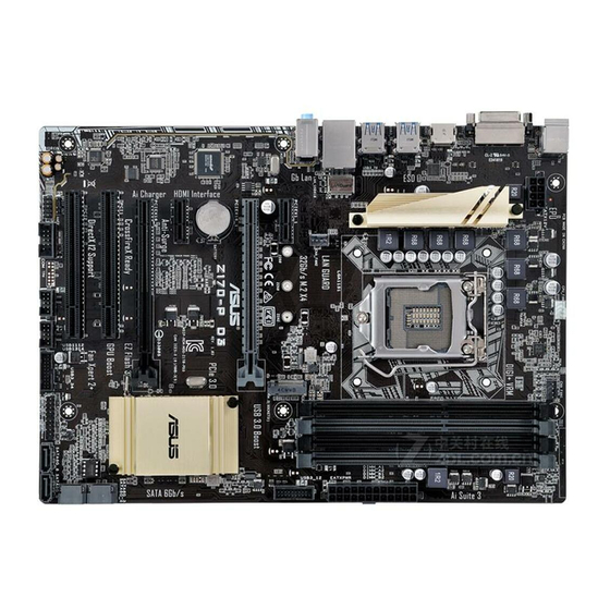
Place this side towards the rear of the chassis Z170-P D3 1.2.3 Motherboard layout 21.8cm(9.6in) CPU_FAN KBMS CHA_FAN1 DIGI +VRM EATX12V HDMI 1442K LGA1151 USB3_56 USB3_78 LAN_USB_910 AUDIO CHA_FAN2 PCIEX1_1 PCIEX16_1 Realtek 8111GR Z170-P D3 BATTERY 1083 Intel ® PCIEX1_2... -
Page 13: Central Processing Unit (Cpu)
1-22 10. Standby power LED (SB_PWR) 1-23 11. USB 2.0 connectors (10-1 pin USB1112, USB1314) 1-15 12. Serial port connectors (10-1 pin COM) 1-15 13. Digital audio connector (4-1 pin SPDIF_OUT) 1-18 14. Front panel audio connector (10-1 pin AAFP) 1-18 Central Processing Unit (CPU) This motherboard comes with a surface mount LGA1151 socket designed for the 6th Generation Intel Core™ i7 / Core™ i5 / Core™ i3, Pentium and Celeron processors. ® ® ® Z170-P D3 Z170-P D3 CPU socket LGA1151 ASUS Z170-P D3... -
Page 14: Installing The Cpu
Unplug all power cables before installing the CPU. • Ensure that you install the correct CPU designed for the LGA1151 socket only. DO NOT install a CPU designed for LGA1150, LGA1155 and LGA1156 sockets on the LGA1151 socket. • Upon purchase of the motherboard, ensure that the PnP cap is on the socket and the socket contacts are not bent. Contact your retailer immediately if the PnP cap is missing, or if you see any damage to the PnP cap/socket contacts/motherboard components. • Keep the cap after installing the motherboard. ASUS will process Return Merchandise Authorization (RMA) requests only if the motherboard comes with the cap on the LGA1151 socket. • The product warranty does not cover damage to the socket contacts resulting from incorrect CPU installation/removal, or misplacement/loss/incorrect removal of the PnP cap. 1.3.1 Installing the CPU Chapter 1: Product introduction... -
Page 15: Cpu Heatsink And Fan Assembly Installation
1.3.2 CPU heatsink and fan assembly installation Apply the Thermal Interface Material to the CPU heatsink and CPU before you install the heatsink and fan if necessary. ASUS Z170-P D3... - Page 16 To install the CPU heatsink and fan assembly To uninstall the CPU heatsink and fan assembly Chapter 1: Product introduction...
-
Page 17: System Memory
System memory 1.4.1 Overview This motherboard comes with four Double Data Rate 3 (DDR3) Dual Inline Memory Module (DIMM) sockets. The figure illustrates the location of the DDR3 DIMM sockets: Z170-P D3 Z170-P D3 240-pin DDR3 DIMM sockets 1.4.2 Memory configurations You may install 2 GB, 4 GB, and 8 GB unbuffered non-ECC DDR3 DIMMs into the DIMM sockets. You can refer to the recommended memory population below. Recommended memory configurations ASUS Z170-P D3... - Page 18 Use a maximum of 3 GB system memory if you are using a 32-bit Windows OS. ® I nstall a 64-bit Windows OS if you want to install 4GB or more on the ® motherboard. F or more details, refer to the Microsoft support site at http://support.microsoft. ® com/kb/929605/en-us. • The default memory operation frequency is dependent on its Serial Presence Detect (SPD), which is the standard way of accessing information from a memory module. Under the default state, some memory modules for overclocking may operate at a lower frequency than the vendor-marked value. To operate at the vendor-marked or at a higher frequency, refer to section 2.5 Ai Tweaker menu for manual memory frequency adjustment. • Always install the DIMMS with the same CAS Latency. For an optimum compatibility, we recommend that you install memory modules of the same version or data code (D/C) from the same vendor. Check with the vendor to get the correct memory modules. • Visit the ASUS website at www.asus.com for the latest QVL. Chapter 1: Product introduction...
-
Page 19: Installing A Dimm
1.4.3 Installing a DIMM To remove a DIMM ASUS Z170-P D3... -
Page 20: Expansion Slots
Expansion slots In the future, you may need to install expansion cards. The following sub-sections describe the slots and the expansion cards that they support. Unplug the power cord before adding or removing expansion cards. Failure to do so may cause you physical injury and damage motherboard components. 1.5.1 Installing an expansion card To install an expansion card: Before installing the expansion card, read the documentation that came with it and make the necessary hardware settings for the card. Remove the system unit cover (if your motherboard is already installed in a chassis). -
Page 21: Irq Assignments For This Motherboard
– – – PCI 1 – shared – – PCI 2 – – shared – Realtek 8111GR LAN – – – shared Controller HD Audio shared – – – SATA Controller shared – – – XHCI Controller shared – – – ASUS Z170-P D3 1-11... -
Page 22: Headers
Clear RTC RAM (2-pin CLRTC) This header allows you to clear the Real Time Clock (RTC) RAM in CMOS. You can clear the CMOS memory of date, time, and system setup parameters by erasing the CMOS RTC RAM data. The onboard button cell battery powers the RAM data in CMOS, which include system setup information such as system passwords. CLRTC Z170-P D3 PIN 1 Z170-P D3 Clear RTC RAM To erase the RTC RAM: Turn OFF the computer and unplug the power cord. Use a metal object such as a screwdriver to short the two pins. Plug the power cord and turn on the computer. Hold down the <Del> key during the boot process and enter BIOS setup to re- enter data. • If the steps above do not help, remove the onboard battery and short the two pins again to clear the CMOS RTC RAM data. After clearing the CMOS, reinstall the... -
Page 23: Connectors
1Gbps connection (Blinking) LAN port Orange Ready to (Blinking then wake up from steady) S5 mode Line In port (light blue). This port connects to the tape, CD, DVD player, or other audio sources. Line Out port (lime). This port connects to a headphone or a speaker. In the 4.1, 5.1 and 7.1-channel configurations, the function of this port becomes Front Speaker Out. Microphone port (pink). This port connects to a microphone. Refer to the audio configuration table for the function of the audio ports in 2.1, 4.1, 5.1, or 7.1-channel configuration. ASUS Z170-P D3 1-13... - Page 24 Audio 2.1, 4.1, 5.1, or 7.1-channel configuration Headset Port 4.1-channel 5.1-channel 7.1-channel 2.1-channel Light Blue (Rear panel) Line In Rear Speaker Out Rear Speaker Out Rear Speaker Out Lime (Rear panel) Line Out Front Speaker Out Front Speaker Out Front Speaker Out Pink (Rear panel) Mic In Mic In Bass/Center Bass/Center Lime (Front panel) Side Speaker Out To configure an 7.1-channel audio output: Use a chassis with HD audio module in the front panel to support an 7.1-channel audio output. USB 2.0 ports. These 4-pin Universal Serial Bus (USB) ports are for USB 2.0/1.1 devices.
-
Page 25: Internal Connectors
1.7.2 Internal connectors Serial port connector (10-1 pin COM) This connector is for a serial (COM) port. Connect the serial port module cable to this connector, then install the module to a slot opening at the back of the system chassis. PIN 1 Z170-P D3 Z170-P D3 Serial port (COM) connector The COM module is purchased separately. USB 2.0 connectors (10-1 pin USB1112, USB1314) These connectors are for USB 2.0 ports. Connect the USB module cable to any of these connectors, then install the module to a slot opening at the back of the system chassis. These USB connectors comply with USB 2.0 specifications and supports up to 480Mbps connection speed. USB1112 USB1314 Z170-P D3 PIN 1 PIN 1 Z170-P D3 USB2.0 connectors... - Page 26 USB 3.0 connectors (20-1 pin USB3_12, USB3_34) These connectors allow you to connect a USB 3.0 module for additional USB 3.0 front or rear panel ports. With an installed USB 3.0 module, you can enjoy all the benefits of USB 3.0 including faster data transfer speeds of up to 5 Gbps, faster charging time for USB-chargeable devices, optimized power efficiency, and backward compatibility with USB 2.0. USB3_12 PIN 1 USB3+5V USB3+5V IntA_P1_SSRX- IntA_P2_SSRX- IntA_P1_SSRX+ IntA_P2_SSRX+ IntA_P1_SSTX- IntA_P2_SSTX- IntA_P1_SSTX+ IntA_P2_SSTX+ IntA_P1_D- IntA_P2_D- IntA_P1_D+ IntA_P2_D+ USB3_34 PIN 1 Z170-P D3 Z170-P D3 USB3.0 Front panel connectors The USB 3.0 module is purchased separately. 1-16 Chapter 1: Product introduction...
- Page 27 -5 Volts PIN 1 +5 Volts +5 Volts PSON# -12 Volts +3 Volts Z170-P D3 +3 Volts +3 Volts PIN 1 Z170-P D3 ATX power connectors • For a fully configured system, we recommend that you use a power supply unit (PSU) that complies with ATX 12 V Specification 2.0 (or later version) and provides a minimum power of 350 W. • DO NOT forget to connect the 4-pin/8-pin ATX +12V power plug. Otherwise, the system will not boot up. • We recommend that you use a PSU with higher power output when configuring a system with more power-consuming devices or when you intend to install additional devices. The system may become unstable or may not boot up if the power is...
-
Page 28: Digital Audio Connector
This connector is for a chassis-mounted front panel audio I/O module that supports either HD Audio or legacy AC`97 audio standard. Connect one end of the front panel audio I/O module cable to this connector. AAFP PIN 1 Z170-P D3 HD-audio-compliant Legacy AC’97 pin definition compliant definition Z170-P D3 Front panel audio connector • We recommend that you connect a high-definition front panel audio module to this connector to avail of the motherboard’s high-definition audio capability. • If you want to connect a high-definition front panel audio module to this connector, set the Front Panel Type item in the BIOS setup to [HD]. If you want to connect an AC’97 front panel audio module to this connector, set the item to [AC97]. By default, this connector is set to [HD]. See section 2.6.7 Onboard Devices Configuration for details. Digital audio connector (4-1 pin SPDIF_OUT) This connector is for an additional Sony/Philips Digital Interface (S/PDIF) port. Connect... - Page 29 M.2 socket 3 This socket allows you to install an M.2 (NGFF) SSD module. M.2(SOCKET3) Z170-P D3 Z170-P D3 M.2(SOCKET3) • This socket supports M Key and 2242/2260/2280 storage devices. • When using Intel Desktop Responsiveness technologies with PCIe/SATA M.2 device, ® ensure to set up the Windows UEFI operating system under RAID mode. ® The M.2 (NGFF) SSD module is purchased separately. ASUS Z170-P D3 1-19...
-
Page 30: Cpu/Chassis Fan Connectors 4-Pin Cpu_Fan/4-Pin Cha_Fan
CPU and chassis fan connectors (4-pin CPU_FAN, 4-pin CHA_FAN 1/2) Connect the fan cables to the fan connectors on the motherboard, ensuring that the black wire of each cable matches the ground pin of the connector CPU_FAN CHA_FAN1 CHA_FAN2 Z170-P D3 CHA FAN PWR CHA FAN IN Z170-P D3 Fan connectors Do not forget to connect the fan cables to the fan connectors. Insufficient air flow inside the system may damage the motherboard components. These are not jumpers! Do not place jumper caps on the fan connectors! The CPU_FAN connector supports a CPU fan of maximum 1A (12 W) fan power. Only the 4-pin CPU fan supports the ASUS Fan Xpert 2+ feature. 1-20 Chapter 1: Product introduction... - Page 31 Z170 Serial ATA 6.0Gb/s connectors (7-pin SATA6G_3~6) ® These connectors connect to Serial ATA 6.0 Gb/s hard disk drives via Serial ATA 6.0 Gb/s signal cables. SATA6G_3 RSATA_TXP1 RSATA_TXN1 RSATA_RXN1 RSATA_RXP1 SATA6G_4 RSATA_TXP2 RSATA_TXN2 RSATA_RXN2 RSATA_RXP2 SATA6G_6 SATA6G_5 Z170-P D3 Z170-P D3 Intel SATA 6.0Gb/s connectors ® When using hot-plug and NCQ, set the SATA Mode Selection item in the BIOS to [AHCI]. See section 2.6.5 SATA Configuration for details. ASUS Z170-P D3 1-21...
-
Page 32: System Panel Connector
System panel connector (20-5 pin PANEL) This connector supports several chassis-mounted functions. PANEL +PWR_LED- SPEAKER PWR_SW PIN 1 Z170-P D3 +HDD_LED- RESET +PWR_LED- * Requires an ATX power supply Z170-P D3 System panel connector • System power LED (4-pin +PWR_LED-) This 2-pin connector is for the system power LED. Connect the chassis power LED cable to this connector. The system power LED lights up when you turn on the system power, and blinks when the system is in sleep mode. • Hard disk drive activity LED (2-pin +HDD_LED-) This 2-pin connector is for the HDD Activity LED. Connect the HDD Activity LED cable to this connector. The HDD LED lights up or flashes when data is read from or written to the HDD. •... -
Page 33: Onboard Led
Onboard LED Standby Power LED (SB_PWR) The motherboard comes with a standby power LED that lights up to indicate that the system is ON, in sleep mode, or in soft-off mode. This is a reminder that you should shut down the system and unplug the power cable before removing or plugging in any motherboard component. The illustration below shows the location of the onboard LED. Z170-P D3 SB_PWR Standby Power Powered Off Z170-P D3 Standby power LED ASUS Z170-P D3 1-23... -
Page 34: Software Support
® ® ® 10 (64-bit) Operating Systems (OS). Always install the latest OS version and corresponding updates to maximize the features of your hardware. Motherboard settings and hardware options vary. Refer to your OS documentation for detailed information. 1.9.2 Support DVD information The Support DVD that comes with the motherboard package contains the drivers, software applications, and utilities that you can install to avail all motherboard features. The contents of the Support DVD are subject to change at any time without notice. Visit the ASUS website at www.asus.com for updates. To run the Support DVD Place the Support DVD into the optical drive. If Autorun is enabled in your computer, the DVD automatically displays the lists of the unique features of your ASUS motherboard. Click the Drivers, Utilities, Manual, or Specials tabs to display their respective menus. The following screen is for reference only. If Autorun is NOT enabled in your computer, browse the contents of the Support DVD to locate the file ASSETUP.EXE from the BIN folder. Double-click the ASSETUP.EXE to run the DVD. 1-24 Chapter 1: Product introduction... -
Page 35: Chapter 2: Bios Information
BIOS and select a boot logo when the system goes into POST. To launch EZ Update, click EZ Update on the AI Suite 3 main menu bar. Click to automatically update your motherboard’s driver, software and firmware Click to find and Click to select Click to select the BIOS a boot logo update the from file BIOS EZ Update requires an Internet connection either through a network or an ISP (Internet Service Provider). ASUS Z170-P D3... -
Page 36: Asus Ez Flash
The ASUS EZ Flash 3 feature allows you to update the BIOS without using an OS-based utility. • Ensure that you load the BIOS default settings to ensure system compatibility and stability. Select the Load Optimized Defaults item under the Exit menu. See section 2.10 Exit Menu for details. • Check your Internet connection before updating the BIOS via the Internet. To update the BIOS using EZ Flash 3: Enter the Advanced Mode of the BIOS setup program. Go to the Tool menu to select ASUS EZ Flash 3 Utility and press <Enter> to enable it. Follow the steps below to update the BIOS via USB or Internet. Via USB Insert the USB flash disk that contains the latest BIOS file to the USB port, then select by USB. Press <Tab> to switch to the Drive field. Press the Up/Down arrow keys to find the USB flash disk that contains the latest BIOS, and then press <Enter>. Press <Tab> to switch to the Folder Info field. Press the Up/Down arrow keys to find the BIOS file, and then press <Enter> to perform the BIOS update process. -
Page 37: Asus Crashfree Bios 3 Utility
Reboot the system when the update process is done. • ASUS EZ Flash 3 supports USB devices, such as a USB flash disk, with FAT 32/16 format and single partition only. • DO NOT shut down or reset the system while updating the BIOS to prevent system boot failure! 2.1.3 ASUS CrashFree BIOS 3 utility The ASUS CrashFree BIOS 3 is an auto recovery tool that allows you to restore the BIOS file when it fails or gets corrupted during the updating process. You can restore a corrupted BIOS file using the motherboard support DVD or a USB flash drive that contains the updated BIOS file. • Before using this utility, rename the BIOS file in the removable device into Z17P3.CAP. • The BIOS file in the support DVD may not be the latest version. Download the latest BIOS file from the ASUS website at www.asus.com. Recovering the BIOS To recover the BIOS: Turn on the system. Insert the support DVD to the optical drive or the USB flash drive that contains the BIOS file to the USB port. The utility automatically checks the devices for the BIOS file. When found, the utility reads the BIOS file and enters ASUS EZ Flash 3 utility automatically. The system requires you to enter BIOS Setup to recover BIOS settings. To ensure system compatibility and stability, we recommend that you press <F5> to load default BIOS values. DO NOT shut down or reset the system while updating the BIOS! Doing so can cause system boot failure! 2.1.4... - Page 38 Please select boot device: and to move selection ENTER to select boot device ESC to boot using defaults P2: ST3808110AS (76319MB) aigo miniking (250MB) UEFI: (FAT) ASUS DRW-2014L1T(4458MB) P1: ASUS DRW-2014L1T(4458MB) UEFI: (FAT) aigo miniking (250MB) Enter Setup 4. When the booting message appears, press <Enter> within five (5) seconds to enter FreeDOS prompt.
-
Page 39: Updating The Bios File
[Enter] Select or Load [Tab] Switch [V] Drive Info [Up/Down/Home/End] Move [Esc] Exit Press <Tab> to switch from Drives panel to Files panel then press <Up/Down or Home/ End> keys to select the BIOS file and press <Enter>. After the BIOS Updater checks the selected BIOS file, select Yes to confirm the BIOS update. Are you sure you want to update the BIOS? The BIOS Backup feature is not supported due to security regulations. Select Yes then press <Enter>. When BIOS update is done, press <ESC> to exit BIOS Updater. Restart your computer. DO NOT shut down or reset the system while updating the BIOS to prevent system boot failaure. Ensure to load the BIOS default settings to ensure system compatibility and stability. Select the Load Optimized Defaults item under the Exit BIOS menu. See section 2.10 Exit Menu for details. ASUS Z170-P D3... -
Page 40: Bios Setup Program
Entering BIOS Setup after POST To enter BIOS Setup after POST: Press <Ctrl>+<Alt>+<Del> simultaneously. Press the reset button on the system chassis. Press the power button to turn the system off then back on. Do this option only if you failed to enter BIOS Setup using the first two options. Using the power button, reset button, or the <Ctrl>+<Alt>+<Del> keys to force reset from a running operating system can cause damage to your data or system. We recommend you always shut down the system properly from the operating system. • The BIOS setup screens shown in this section are for reference purposes only, and may not exactly match what you see on your screen. • Visit the ASUS website at www.asus.com to download the latest BIOS file for this motherboard. • Ensure that a mouse is connected to your motherboard if you want to use the mouse to control the BIOS setup program. • If the system becomes unstable after changing any BIOS setting, load the default settings to ensure system compatibility and stability. Select the Load Optimized Defaults item under the Exit menu or press hotkey F5. See section 2.10 Exit Menu for details. • If the system fails to boot after changing any BIOS setting, try to clear the CMOS and reset the motherboard to the default value. See section 1.6 Headers for information on how to erase the RTC RAM. - Page 41 FAQs bootable optimized Displays the CPU Fan’s speed. devices default Click the button to manually settings Selects the boot Displays the tune the fans device priority Advanced Saves the changes mode menus and resets the system The boot device options vary depending on the devices you installed to the system. ASUS Z170-P D3...
-
Page 42: Advanced Mode
2.2.2 Advanced Mode The Advanced Mode provides advanced options for experienced end-users to configure the BIOS settings. The figure below shows an example of the Advanced Mode. Refer to the following sections for the detailed configurations. To access the EZ Mode, click EzMode(F7) or press <F7>. Q-Fan control EZ Tuning Wizard MyFavorite Quick Note Language Hot Keys Menu bar Last modified Sub-menu item Configuration Item settings fields description Menu items Goes back to EZ Mode Displays the CPU/motherboard temperature, CPU and memory voltage output Chapter 2: Getting started... -
Page 43: Menu Bar
The other items (My Favorites, Ai Tweaker, Advanced, Monitor, Boot, Tool, and Exit) on the menu bar have their respective menu items. Submenu items A greater than sign (>) before each item on any menu screen means that the item has a submenu. To display the submenu, select the item and press <Enter>. Language This button above the menu bar contains the languages that you can select for your BIOS. Click this button to select the language that you want to display in your BIOS screen. MyFavorites (F3) This button above the menu bar shows all BIOS items in a Tree Map setup. Select frequently- used BIOS settings and save it to MyFavorites menu. Refer to section 2.3 My Favorites for more information. Q-Fan Control (F6) This button above the menu bar displays the current settings of your fans. Use this button to manually tweak the fans to your desired settings. Refer to section 2.2.3 QFan Control for more information. EZ Tuning Wizard (F11) This button above the menu bar allows you to view and tweak the overclocking settings of your system. It also allows you to change the motherboard’s SATA mode from AHCI to RAID mode. Refer to section 2.2.4 EZ Tuning Wizard for more information. ASUS Z170-P D3... -
Page 44: Hot Keys
Search on FAQ Move your mouse over this button to show a QR code. Scan this QR code with your mobile device to connect to the ASUS BIOS FAQ web page. You can also scan the QR code below. Quick Note (F9) This button above the menu bar allows you to key in notes of the activities that you have done in BIOS. • The Quick Note function does not support the following keyboard functions: delete, cut, copy and paste. • You can only use the alphanumeric characters to enter your notes. Hot keys This button above the menu bar contains the navigation keys for the BIOS setup program. Use the navigation keys to select items in the menu and change the settings. Scroll bar A scroll bar appears on the right side of a menu screen when there are items that do not fit on the screen. Press the Up/Down arrow keys or <Page Up> / <Page Down> keys to display the other items on the screen. General help At the top right corner of the menu screen is a brief description of the selected item. Use <F12> key to capture the BIOS screen and save it to the removable storage device. Configuration fields These fields show the values for the menu items. If an item is user-configurable, you can change the value of the field opposite the item. You cannot select an item that is not user-configurable. A configurable field is highlighted when selected. To change the value of a field, select it and press <Enter> to display a list of options. Last Modified button This button shows the items that you last modified and saved in BIOS Setup. 2-10... -
Page 45: Qfan Control
The QFan Control allows you to set a fan profile or manually configure the operating speed of your CPU and chassis fans. Click to select a fan to be configured Select a profile to apply Click to apply to your fans the fan setting Click to undo Click to the changes go back to main menu ASUS Z170-P D3 2-11... -
Page 46: Configuring Fans Manually
Configuring fans manually Select Manual from the list of profiles to manually configure your fans’ operating speed. Click to manually Speed points configure your fans To configure your fans: Select the fan that you want to configure and to view its current status. Click and drag the speed points to adjust the fans’ operating speed. Click Apply to save the changes then click Exit (ESC). 2-12 Chapter 2: Getting started... -
Page 47: Ez Tuning Wizard
2.2.4 EZ Tuning Wizard EZ Tuning Wizard allows you to overclock your CPU and DRAM, computer usage, and CPU fan to their best settings. You can also easily set RAID in your system using this feature. OC setup RAID setup Tuning your system settings To tune your settings: Press <F11> on your keyboard or click from the BIOS screen to open EZ Tuning Wizard screen, then click Next. Select a PC scenario Daily Computing or Gaming/Media Editing, then click Next. Select the CPU fan type (Box cooler, Tower cooler, or Water cooler) that you installed then click Next. If you are not sure of the CPU fan type, click I’m not sure. The system automatically detects the CPU fan type. Click Next then click Yes to confirm auto-tuning. ASUS Z170-P D3 2-13... -
Page 48: Creating Raid
Creating RAID To create RAID: Press <F11> on your keyboard or click from the BIOS screen to open EZ Tuning Wizard screen. Click RAID then click Next. • Ensure that your HDDs have no existing RAID volumes. • Ensure to connect your HDDs to Intel SATA connectors. ® Select the type of storage for your RAID Easy Backup or Super Speed, then click Next. For Easy Backup, click Next then select from Easy Backup (RAID1) or Easy Backup (RAID10). You can only select Easy Backup (RAID 10) if you connect four (4) HDDs. For Super Speed, click Next then select from Super Speed (RAID0) or Super Speed (RAID5). After selecting the type of RAID, click Next then click Yes to continue the RAID setup. After the RAID setup is done, click Yes to exit the setup then click OK to reset your system. 2-14 Chapter 2: Getting started... -
Page 49: My Favorites
My Favorites MyFavorites is your personal space where you can easily save and access your favorite BIOS items. ASUS Z170-P D3 2-15... - Page 50 Adding items to My Favorites To add BIOS items: Press <F3> on your keyboard or click from the BIOS screen to open Setup Tree Map screen. On the Setup Tree Map screen, select the BIOS items that you want to save in MyFavorites screen. Main menu panel Selected shortcut items Submenu panel Select an item from main menu panel, then click the submenu that you want to save as favorite from the submenu panel and click You cannot add the following items to My Favorite items: • User-managed items such as language and boot order Click Exit (ESC) or press <esc> key to close Setup Tree Map screen. Go to My Favorites menu to view the saved BIOS items. 2-16 Chapter 2: Getting started...
-
Page 51: Main Menu
Main menu The Main menu screen appears when you enter the Advanced Mode of the BIOS Setup program. The Main menu provides you an overview of the basic system information, and allows you to set the system date, time, language, and security settings. 2.4.1 Language [English] Allows you to choose the BIOS language version from the options. Configuration options: [English] [Español] [Русский] [한국어] 2.4.2 Security The Security menu items allow you to change the system security settings. • If you have forgotten your BIOS password, erase the CMOS Real Time Clock (RTC) RAM to clear the BIOS password. See section 1.6 Headers for information on how to erase the RTC RAM. • The Administrator or User Password items on top of the screen show the default Not Installed. After you set a password, these items show Installed. ASUS Z170-P D3 2-17... -
Page 52: Administrator Password
Administrator Password If you have set an administrator password, we recommend that you enter the administrator password for accessing the system. To set an administrator password: Select the Administrator Password item and press <Enter>. From the Create New Password box, key in a password, then press <Enter>. Confirm the password when prompted. To change an administrator password: Select the Administrator Password item and press <Enter>. From the Enter Current Password box, key in the current password, then press <Enter>. From the Create New Password box, key in a new password, then press <Enter>. Confirm the password when prompted. To clear the administrator password, follow the same steps as in changing an administrator password, but press <Enter> when prompted to create/confirm the password. After you clear the password, the Administrator Password item on top of the screen shows Not Installed. User Password If you have set a user password, you must enter the user password for accessing the system. The User Password item on top of the screen shows the default Not Installed. After you set a password, this item shows Installed. -
Page 53: Ai Tweaker Menu
Ai Tweaker menu The Ai Tweaker menu items allow you to configure overclocking-related items. Be cautious when changing the settings of the Ai Tweaker menu items. Incorrect field values can cause the system to malfunction. The configuration options for this section vary depending on the CPU and DIMM model you installed on the motherboard. Scroll down to display other BIOS items. 2.5.1 Ai Overclock Tuner [Auto] This item allows you to select the CPU overclocking options to achieve the desired CPU internal frequency. Select any of these preset overclocking configuration options: [Auto] Loads the optimal settings for the system automatically. [Manual] Allows you to assign the BCLK (base clock) frequency manually. The following items appear only when you set the Ai Overclocking Tuner to [Manual]. ASUS Z170-P D3 2-19... - Page 54 BCLK Frequency [100] This item allows you to set the BCLK (base clock) frequency to enhance the system performance. Use the <+> or <-> to adjust the value. The values range from 40.0 MHz to 340.0 MHz. We recommend you to set the value based on the CPU specification, as high BCLK frequencies may damage the CPU permanently. BCLK Spread Spectrum [Auto] This item allows you to start overclocking the system from the initial BCLK (base clock) frequency to the assigned BCLK frequency. Use the <+> or <-> to adjust the value. The value ranges depend on the value you set on BCLK Frequency. 2.5.2 ASUS MultiCore Enhancement [Auto] [Auto] This item allows you to maximize the oveclocking performance optimized by ASUS core ratio settings. [Disabled] This item allows you to set to default core ratio settings. 2.5.3 CPU Core Ratio [Auto] This item allows you to set the CPU core ratio limit per core or synchronize automatically to all cores. Configuration options: [Auto] [Sync All Cores] [Per Core] When the CPU Core Ratio is set to [Sync All Cores] or [Per Core], the following items appear. 1-Core Ratio Limit [Auto] Select [Auto] to apply the CPU default Turbo Ratio setting or manually assign a 1-Core Limit value that must be higher than or equal to the 2-Core Ratio Limit.
-
Page 55: Cpu Svid Support
Settings] [Ratio Tuning] [BCLK + Ratio Tuning] Ensure that you installed an efficient CPU fan for CPU and graphics loading before selecting either [Ratio Tuning] or [BCLK + Ratio Tuning]. To keep the current overclocking settings, select [Keep Current Settings]. 2.5.8 GPU Boost [Keep Current Settings] Enable this item to accelerate the integrated GPU for extreme graphics performance. Configuration options: [Keep Current Settings] [Enabled] 2.5.9 EPU Power Saving Mode [Disabled] ASUS EPU (Energy Processing Unit) sets the CPU in its minimum power consumption settings. Enable this item to set lower CPU VCCIN and Vcore voltages and achieve the best energy saving condition. Configuration options: [Disabled] [Enabled] 2.5.10 CPU SVID Support [Auto] Disabling SVID Support stops the processor from commmunicating with the external voltage regulator. Configuration options: [Auto] [Disabled] [Enabled] ASUS Z170-P D3 2-21... -
Page 56: Dram Timing Control
2.5.10 DRAM Timing Control The subitems in this menu allow you to set the DRAM timing control features. Use the <+> and <-> keys to adjust the value. To restore the default setting, type [auto] using the keyboard and press the <Enter> key. Changing the values in this menu may cause the system to become unstable! If this happens, revert to the default settings. 2.5.11 DIGI+ VRM CPU Load-Line Calibration [Auto] Load-line is defined by Intel VRM specification and affects the CPU power voltage. The CPU working voltage will decrease proportionally depending on the CPU loading. Higher levels of the load-line calibration can get a higher voltage and a better overclocking performance but increases the CPU and VRM thermal. Configuration options: [Auto] [Level 1-7] The boosted performance may vary depending on the CPU specification. Do not remove the thermal module. CPU VRM Switching Frequency [Auto] This item affects the VRM transient response speed and the component thermal production. Select [Manual] to configure a higher frequency for a quicker transient response speed. Configuration options: [Auto] [Manual] DO NOT remove the thermal module. The thermal conditions should be monitored. The following item appears only when you set the CPU VRM Switching Frequency to [Manual]. Fixed CPU VRM Switching Frequency (KHz) [250] This item allows you to set a higher frequency for a quicker transient response speed. - Page 57 GT and VRM thermal conditions. Select from level 1 to 8 to adjust the GT power voltage from 0% to 100%. The actual performance boost may vary depending on the GT specification. Do not remove the thermal module. CPU Graphics Current Capability [Auto] This item allows you to adjust the total power range for GT overclocking. A higher value provides a wider total power range and extends the overclocking frequency range simultaneously. Configuration options: [Auto] [100%] [110%] [120%] [130%] [140%] Choose a higher value when overclocking, or under a high GT loading for extra power support. CPU Graphics Switching Frequency [Auto] This item affects the GT transient response speed and the component thermal production. Select [Manual] to configure a higher frequency for a quicker transient response speed. Configuration options: [Auto] [Manual] DO NOT remove the thermal module. The thermal conditions should be monitored. The following items appear only when you set the GT Switching Frequency to [Manual]. CPU Graphics Power Duty Control [T.Probe] DIGI+ VRM Duty Control adjusts the current and thermal conditions of every component’s phase. [T.Probe] Select to maintain the VRM thermal balance. [Extreme] Select to maintain the current VRM balance. ASUS Z170-P D3 2-23...
- Page 58 CPU Graphics Phase Control [Auto] This item allows you to set the power phase control of the CPU. Configuration options: [Auto] [Standard] [Optimized] [Extreme] [Power Phase Response] DO NOT remove the thermal module when setting this item to [Power Phase Response]. The thermal conditions should be monitored. The following items appear only when you set the GT Power Phase Control to [Power Phase Response]. 2.5.12 Internal CPU Power Management The subitems in this menu allow you to set the CPU ratio and their features. Intel SpeedStep™ Technology [Enabled] ® This item allows the operating system to dynamically adjust the processor voltage and cores frequency, resulting to a decreased average power consumption and decreased average heat production. Configuration options: [Disabled] [Enabled] Turbo Mode [Enabled] This item allows you to enable your core processor’s speed to run faster than the base operating frequency when it is below operating power, current and temperature specification limit. Configuration options: [Disabled] [Enabled] The following items appear only when you set the Turbo Mode to [Enabled]. Turbo Mode Parameters Long Duration Package Power Limit [Auto] Allows you to limit the Turbo Ratio’s time duration that exceeds the TDP (Thermal Design Power) for maximum performance. Use the <+> or <-> keys to adjust the value.
- Page 59 Max. CPU Cache Ratio [Auto] Allows you to set the maximum possible CPU cache ratio. Use the <+> or <-> keys to adjust the value. The values range from 8 to 83 with a 1 interval. 2.5.17 Max. CPU Graphics Ratio [Auto] Allows you to set the maximum possible CPU graphics ratio. Use the <+> or <-> keys to adjust the value. The values range from 1 to 60 with a 1 interval. 2.5.18 CPU Core/Cache Voltage [Auto] This item allows you to configure the amount of voltage fed to the CPU cores or CPU uncores including its cache. Increase the voltage when setting a high Core Frequency value or a high CPU cache frequency. Configuration options: [Auto] [Manual Mode] [Offset Mode] [Adaptive Mode] • The following item appears only when you set the CPU Core Voltage to [Manual Mode]. • [Adaptive Mode] is available for some specific CPU types. CPU Core Voltage Override [Auto] Allows you to set the CPU Core Voltage override. Use the <+> or <-> keys to adjust the value. The values range from 0.001V to 0.635V with a 0.001V interval. ASUS Z170-P D3 2-25...
- Page 60 The following items appear only when you set the CPU Core Voltage to [Offset Mode] or [Adaptive Mode]. Offset Mode Sign [+] [+] To offset the voltage by a positive value. [–] To offset the voltage by a negative value. CPU Core Voltage Offset Use the <+> or <-> keys to adjust the value. The values range from 0.001V to 0.999V with a 0.001V interval. The following item appears only when you set the CPU Core Voltage to [Adaptive Mode]. Additional Turbo Mode CPU Core Voltage [Auto] This item allows you to set the amount of voltage fed to the CPU cores when running in turbo mode. Increase the voltage when configuring a high CPU core frequency. The voltage you set is affected by the offset value. Use the <+> or <-> keys to adjust the value. The values range from 0.001V to 1.920 V with a 0.001 V interval. Total Adaptive Mode CPU Core Voltage [Auto] This item sums up the voltages of the CPU Core Voltage offset and Additional Turbo Mode CPU Core Voltage options.
- Page 61 2.5.23 PCH Core Voltage [Auto] This item allows you to set the PCH core voltage. Use the <+> and <-> keys to adjust the value. The values range from 1.0V to 1.15V with a 0.05V interval. 2.5.24 DRAM REF Voltage Control [Auto] The subitems in this menu allows you to set the DRAM reference voltage on the control lines from the memory bus. You can use the <+> or <-> keys to adjust the value. The values range from 0.39500V to 0.63000V with a 0.00500V interval. DRAM CTRL REF Voltage [Auto] This item allows you to set the DRAM reference voltage on the control lines from the memory bus. You can use the <+> or <-> keys to adjust the value. The values range from 0.39500V to 0.63000V with a 0.00500V interval. DRAM DATA REF Voltage on CHA/CHB [Auto] This item allows you to set the DRAM reference voltage on the data lines on Channels A and B. You can use the <+> or <-> keys to adjust the value. The values range from 0.39500V to 0.63000V with a 0.00500V interval. To set a value for the DRAM reference voltage, we recommend you to set a value close to the standard value which is 0.500000x. ASUS Z170-P D3 2-27...
-
Page 62: Advanced Menu
Advanced menu The Advanced menu items allow you to change the settings for the CPU and other system devices. Be cautious when changing the settings of the Advanced menu items. Incorrect field values can cause the system to malfunction. 2.6.1 CPU Configuration The items in this menu show the CPU-related information that the BIOS automatically detects. The items shown in submenu may be different due to the CPU you installed. Hyper-threading [Enabled] The Intel Hyper-Threading Technology allows a hyper-threading processor to appear as two logical processors to the operating system, allowing the operating system to schedule two threads or processes simultaneously. [Enabled] Two threads per activated core are enabled. [Disabled] Only one thread per activated core is enabled. 2-28 Chapter 2: Getting started... -
Page 63: Cpu Power Management Configuration
Boot Performance Mode [Auto] This item allows you to select the CPU performance state during system boot before the operating system takes control. The CPU runs at a selected performance ratio based on CPU configuration. Configuration options: [Max Battery] [Max Non-Turbo Performance] [Turbo Performance] [Auto] CPU Power Management Configuration This item allows you to manage and configure the CPU’s power. Intel SpeedStep [Enabled] ® This item allows the operating system to dynamically adjust the processor voltage and cores frequency, resulting to a decreased average power consumption and decreased average heat production. Configuration options: [Disabled] [Enabled] Turbo Mode [Enabled] This item allows you to enable your core processor’s speed to run faster than the base operating frequency when it is below operating power, current and temperature specification limit. Configuration options: [Disabled] [Enabled] CPU C states [Enabled] This item allows you to set the power saving of the CPU states. Configuration options: [Disabled] [Enabled] The following items appear only when you set the CPU C-States to [Enabled]. Enhanced C states [Enabled] This item allows your CPU to reduce power consumption when the system is in idle mode. Configuration options: [Enabled] [Disabled] ASUS Z170-P D3 2-29... -
Page 64: Platform Misc Configuration
CPU C3 Report [Enabled] This item allows you to disable or enable the CPU C3 report to the operating system. Configuration options: [Enabled] [Disabled] CPU C6 Report [Enabled] This item allows you to disable or enable the CPU C6 report to the operating system. Configuration options: [Enabled] [Disabled] CPU C7 Report [Enabled] This item allows you to disable or enable the CPU C7 report to the operating system. Configuration options: [Enabled] [Disabled] CPU C8 Report [Enabled] This item allows you to disable or enable the CPU C8 report to the operating system. Configuration options: [Enabled] [Disabled] 2.6.2 Platform Misc Configuration The items in this menu allow you to configure the platform-related features. PCI-E Native Power Management [Disabled] This item allows you to enhance the power saving feature of PCI Express and perform ASPM operations in the operating system. Configuration options: [Disabled] [Enabled] The following item appears only when you set the PCI Express Native Power Management to [Enabled]. Native ASPM [Disabled] [Enabled] Windows Vista OS controls the ASPM (active state power... -
Page 65: Graphics Configuration
Configuration options: [Disabled] [Enabled] DMI/OPI Configuration This item allows you to control various DMI (direct media interface) to run at PCI-E 2.0 speed. DMI Max Link Speed [Gen2] Allows you to configure the DMI speed. Configuration options: [Auto] [Gen1] [Gen2] [Gen3] PEG Port Configuration Allows you to configure the PEG Port settings. Enable Root Port [Auto] Allows you to enable or disable the root port. Configuration options: [Auto] [Disabled] [Enabled] PCIEx16_1 Link Speed [Auto] Allows you to configure the PCIEx16 speed for slot 1. Configuration options: [Auto] [Gen1] [Gen2] [Gen3] Memory Configuration Allows you to configure the memory configuration parameters. Memory Remap [Enabled] Set this item to [Enabled] to support DRAM address remapping for 64-bit operating systems. Configuration options: [Enabled] [Disabled] ASUS Z170-P D3 2-31... -
Page 66: Sata Configuration
2.6.4 PCH IO Configuration This item allows you to configure the PCI Express configuration settings. PCIe Speed [Auto] Allows you to configure the PCIe speed. Configuration options: [Auto] [Gen1] [Gen2] [Gen3] 2.6.5 SATA Configuration While entering Setup, the BIOS automatically detects the presence of SATA devices. The SATA Port items show Not Present if no SATA device is installed to the corresponding SATA port. Hyper Kit Mode [Disabled] Disable this option for M.2 devices. Enable this option for ASUS Hyper Kit card. Configuration options: [Disabled] [Enabled] SATA Controller(s) [Enabled] Enables or disables onboard the SATA device. Configuration options: [Disabled] [Enabled] The following items appear only when you set the SATA Controller(s) to [Enabled]. SATA Mode Selection [AHCI] Allows you to set the SATA configuration. [AHCI] Set to [AHCI] when you want the SATA hard disk drives to use the AHCI (Advanced Host Controller Interface). The AHCI allows the onboard storage driver to enable advanced Serial ATA features that increases storage performance on random workloads by allowing the drive to internally optimize the order of commands. [RAID] S et to [RAID Mode] when you want to create a RAID configuration from the SATA hard disk drives. -
Page 67: Usb Configuration
The USB Devices item shows the auto-detected values. If no USB device is detected, the item shows None. Legacy USB Support [Enabled] [Enabled] Your system supports the USB devices in legacy operating systems. [Disabled] Your USB devices can be used for BIOS setup only and cannot be recognized in the boot devices list. [Auto] Your system automatically detects the presence of USB devices at startup. If any USB devices are detected, the legacy USB support is enabled. XHCI Hand-off [Disabled] [Enabled] Enables the support for operating systems without an XHCI hand-off feature. [Disabled] Disables the XHCI Hand-off support. USB Single Port Control USB_9/10/11/12/13/14 [Enabled] Allows you to enable/disable USB_9/10/11/12/13/14 port. Configuration options: [Disabled] [Enabled] USB3_1/2/3/4/5/6/7/8 [Enabled] Allows you to enable/disable USB3_1/2/3/4/5/6/7/8 port. Configuration options: [Disabled] [Enabled] ASUS Z170-P D3 2-33... -
Page 68: Onboard Devices Configuration
2.6.7 Onboard Devices Configuration HD Audio Controller [Enabled] [Enabled] Enables the HD Audio Device. [Disabled] Disables the HD Audio Device. The following two items appear only when you set the HD Audio Controller item to [Enabled]. Front Panel Type [HD Audio] Allows you to set the front panel audio connector (AAFP) mode to legacy AC’97 or high-definition audio depending on the audio standard that the front panel audio module supports. [HD] Sets the front panel audio connector (AAFP) mode to high definition audio. [AC97] Sets the front panel audio connector (AAFP) mode to legacy AC’97 SPDIF Out Type [SPDIF] [SPDIF] Sets to an SPDIF audio output. [HDMI] Sets to an HDMI audio output. Realtek LAN Controller [On] [On] Enables the Realtek LAN controller. -
Page 69: Network Stack Configuration
Power On By Ring [Disabled] [Disabled] Disables Ring to generate a wake event. [Enabled] Enables Ring to generate a wake event. Power On By RTC [Disabled] [Disabled] Disables RTC to generate a wake event. [Enabled] When set to [Enabled], the items RTC Alarm Date (Days) and Hour/ Minute/Second will become user-configurable with set values. 2.6.9 Network Stack Configuration Network Stack [Disabled] This item allows user to disable or enable the UEFI network stack. Configuration options: [Disabled] [Enabled] The following two items appear only when you set the previous item to [Enabled]. Ipv4 / Ipv6 PXE Support [Enabled] This item allows you to enable or disable the Ipv4/Ipv6 PXE wake event. Configuration options: [Disabled] [Enabled] ASUS Z170-P D3 2-35... -
Page 70: Monitor Menu
Monitor menu The Monitor menu displays the system temperature/power status, and allows you to change the fan settings. Scroll down to display the other BIOS items. 2.7.1 CPU/ MB Temperature [xxxºC/xxxºF]/ [Ignore] The onboard hardware monitor automatically detects and displays the CPU and motherboard temperatures. Select [Ignore] if you do not wish to display the detected temperatures. 2.7.2 CPU Fan/ Chassis Fan 1/2 Speed [xxxx RPM]/ [Ignore]/ [N/A] The onboard hardware monitor automatically detects and displays the CPU and chassis fan 1/2 speeds in rotations per minute (RPM). If the fan is not connected to the motherboard, the field shows N/A. Select [Ignore] if you do not wish to display the detected speed. 2.7.3 CPU Core Voltage, 3.3V Voltage, 5V Voltage, 12V Voltage The onboard hardware monitor automatically detects the voltage output through the onboard voltage regulators. Select [Ignore] if you do not want to detect this item. 2.7.4 CPU Q-Fan Control [PWM Mode] [Disabled] Disables the CPU Q-Fan control feature. - Page 71 CPU Fan Max. Duty Cycle(%) [100] Use the <+> and <-> keys to adjust the maximum CPU fan duty cycle. The values range from 20% to 100%. When the CPU temperature reaches the upper limit, the CPU fan will operate at the maximum duty cycle. CPU Middle Temperature [25] Use the <+> or <-> keys to set the value for CPU Middle Temperature. The range of the values depends on the CPU installed. CPU Fan Middle Duty Cycle(%) [20] Use the <+> or <-> keys to adjust the CPU fan middle duty cycle. The values range from 20% to 100%. When the CPU temperature reaches the upper limit, the CPU fan operates at the maximum duty cycle. CPU Lower Temperature [20] Use the <+> or <-> keys to adjust the CPU fan’s lower temperature. The values range from 20°C to 75°C. CPU Fan Min. Duty Cycle(%) [20] Use the <+> and <-> keys to adjust the minimum CPU fan duty cycle. The values range from 20% to 100%. When the CPU temperature is under the lower limit, the CPU fan will operate at the minimum duty cycle. ASUS Z170-P D3 2-37...
- Page 72 2.7.5 Chassis Fan 1/2 Q-Fan Control [DC Mode] [PWM mode] Enables the chassis Q-Fan control in PWM mode for 4-pin chassis fan. [DC mode] Enables the chassis Q-Fan control in DC mode for 3-pin chassis fan. [Disabled] Disables the chassis Q-Fan control feature. The following items appear only when you set the Chassis Fan 1/2 Q-Fan Control to [PWM Mode] or [DC Mode]. Chassis Fan 1/2 Q-Fan Source [CPU] This item controls the assigned fan according to the selected temperature source. Configuration options: [CPU] [MB] Chassis Fan 1/2 Speed Low Limit [600 RPM] This item allows you to disable or set the chassis fan warning speed. Configuration options: [Ignore] [200RPM] [300 RPM] [400 RPM] [500 RPM] [600 RPM] Chassis Fan 1/2 Profile [Standard] This item allows you to set the appropriate performance level of the chassis fan.
-
Page 73: Boot Menu
Allow Fan Stop [Disabled] This function allows the fan to run at 0% duty cycle when the temperature of the source is dropped below the lower temperature. 2.7.6 Anti Surge Support [On] This item allows you to enable or disable the Anti Surge function. Configuration options: [On] [Off] Boot menu The Boot menu items allow you to change the system boot options. Scroll down to display the other BIOS items. 2.8.1 Fast Boot [Enabled] [Enabled] Select to accelerate the boot speed. [Disabled] Select to go back to normal boot speed. Next Boot after AC Power Loss [Normal Boot] [Normal Boot] Returns to normal boot on the next boot after AC power loss. [Fast Boot] Accelerates the boot speed on the next boot after AC power loss. ASUS Z170-P D3 2-39... - Page 74 2.8.2 Boot Logo Display [Auto] [Auto] Adjusts logo automatically based on Windows display requirements. ® [Full Screen] Maximize the boot logo size. [Disabled] Hide the logo during POST. POST Delay Time [3 sec] This item appears only when you set Boot Logo Display to [Auto] and [Full Screen]. This item allows you to select the desired additional POST waiting time to easily enter the BIOS setup. You can only execute the POST delay time during Normal Boot. The values range from 0 to 10 seconds. This feature will only work under normal boot. Post Report [5 sec] This item appears only when you set Boot Logo Display to [Disabled]. This item allows you to select a desired post report waiting time. Configuration options: [1 sec] ~ [10 sec] [Until Press ESC]. 2.8.3 Bootup NumLock State [Enabled] This item allows you to enable or disable power-on state of the NumLock. Configuration options: [Disabled] [Enabled] 2.8.4 Wait for ‘F1’ If Error [Enabled] When this item is set to [Enabled], the system waits for the F1 key to be pressed when error occurs. Configuration options: [Disabled] [Enabled] 2.8.5...
-
Page 75: Secure Boot
(PK), Key-exchange Key (KEK), Signature database (db), and Revoked Signatures (dbx). When the default Secure boot keys are loaded, all the Secure Boot keys’ state will change from Unloaded mode to loaded mode. Clear Secure Boot keys This item appears only when you load the default Secure Boot keys. This item allows you to clear all the previously applied Secure Boot keys. Save Secure Boot Keys This item allows you to save all the Secure Boot keys to a USB storage device. PK Management The Platform Key (PK) locks and secures the firmware from any non-permissible changes. The system verifies the PK before your system enters the OS. Delete PK Allows you to delete the PK from your system. Once the PK is deleted, all the system’s Secure Boot keys will not be active. Load Default PK Select Yes to load the system default PK or select No to load a downloaded PK from a USB storage device. The PK file must be formatted as a UEFI variable structure with time-based authenticated variable. KEK Management The KEK (Key-exchange Key or Key Enrollment Key) manages the Signature database (db) and Revoked Signature database (dbx). Key-exchange Key (KEK) refers to Microsoft Secure Boot Key-Enrollment Key (KEK). ® ASUS Z170-P D3 2-41... - Page 76 Delete KEK Allows you to delete the KEK from your system. Once the KEK is deleted, the db and the dbx cannot be updated in the operating system. Load Default KEK Select Yes to load the system default KEK or select No to load a downloaded KEK from a USB storage device. Append Default KEK Select Yes to append the system default KEK or select No to append a downloaded additional KEK from a USB storage device for the db and dbx management. The KEK file must be formatted as a UEFI variable structure with time-based authenticated variable. DB Management The db (Authorized Signature database) lists the signers or images of UEFI applications, operating system loaders, and UEFI drivers that you can load on the single computer. Delete the db Allows you to delete the db file from your system. Doing so may cause boot failures. Load Default db Select Yes to load the system default db or select No to load a downloaded db from a USB storage device. Append Default db Select Yes to append the system default db or select No to append a downloaded additional db from a USB storage device to load certain customized UEFI executable files. • The DB file must be formatted as a UEFI variable structure with time-based authenticated variable. • UEFI executable files include UEFI boot devices, drivers and applications dbx Management The dbx (Revoked Signature database) lists the forbidden images of db items that are...
-
Page 77: Tool Menu
• To access Windows OS in Safe Mode, press <F8 > after POST (Windows 8 not supported). • To select the boot device during system startup, press <F8> when ASUS Logo appears. 2.8.10 Boot Override These items displays the available devices. The number of device items that appears on the screen depends on the number of devices installed in the system. Click an item to start booting from the selected device. Tool menu The Tool menu items allow you to configure options for special functions. Select an item then press <Enter> to display the submenu. 2.9.1 ASUS EZ Flash 3 Utility Allows you to run ASUS EZ Flash 3. Press [Enter] to launch the ASUS EZ Flash 3 screen. For more details, see section 2.1.2 ASUS EZ Flash 3. 2.9.2 Setup Animator [Disabled] Enables or disables the Setup animator. Configuration options: [Disabled] [Enabled] ASUS Z170-P D3 2-43... -
Page 78: Asus Overclocking Profile
2.9.3 ASUS Overclocking Profile This item allows you to store or load multiple BIOS settings. The Overclocking Profile items show Not assigned if no profile is created. Load from Profile Allows you to load the previous BIOS settings saved in the BIOS Flash. Key in the profile number that saved your CMOS settings, press <Enter>, and then select Yes. • DO NOT shut down or reset the system while updating the BIOS to prevent the system boot failure! • We recommend that you update the BIOS file only coming from the same memory/ CPU configuration and BIOS version. Profile Name Allows you to create a name for the profile you want to save. Save to Profile Allows you to save the current BIOS settings to the BIOS Flash, and create a profile. Key in a profile number from one to eight, press <Enter>, and then select Yes. Load/Save Profile from/to USB Drive This item allows you to load or save profile from your USB drive, load and save profile to your USB drive. 2.9.4 ASUS SPD Information... -
Page 79: Exit Menu
2.10 Exit menu The Exit menu items allow you to load the optimal default values for the BIOS items, and save or discard your changes to the BIOS items. Load Optimized Defaults This option allows you to load the default values for each of the parameters on the Setup menus. When you select this option or if you press <F5>, a confirmation window appears. Select OK to load the default values. Save Changes & Reset Once you are finished making your selections, choose this option from the Exit menu to ensure the values you selected are saved. When you select this option or if you press <F10>, a confirmation window appears. Select OK to save changes and exit. Discard Changes & Exit This option allows you to exit the Setup program without saving your changes. When you select this option or if you press <Esc>, a confirmation window appears. Select OK to discard changes and exit. Launch EFI Shell from USB drives This option allows you to attempt to launch the EFI Shell application (shellx64.efi) from one of the available USB devices. ASUS Z170-P D3 2-45... - Page 80 2-46 Chapter 2: Getting started...
-
Page 81: Appendices
Cet appareil est conforme aux normes CNR exemptes de licence d’Industrie Canada. Le fonctionnement est soumis aux deux conditions suivantes : (1) cet appareil ne doit pas provoquer d’interférences et (2) cet appareil doit accepter toute interférence, y compris celles susceptibles de provoquer un fonctionnement non souhaité de l’appareil. ASUS Z170-P D3... -
Page 82: Canadian Department Of Communications Statement
ASUS Recycling/Takeback Services ASUS recycling and takeback programs come from our commitment to the highest standards for protecting our environment. We believe in providing solutions for you to be able to responsibly recycle our products, batteries, other components as well as the packaging materials. - Page 83 CE. das Diretivas da CE. Para mais detalhes, consulte a Declaração de Компания ASUS заявляет, что это устройство соответствует основным Conformidade CE. требованиям и другим соответствующим условиям европейских директив. Подробную информацию, пожалуйста, смотрите в декларации...
-
Page 84: Asus Contact Information
+1-510-739-3777 +1-510-608-4555 Web site http://www.asus.com/us/ Technical Support Support fax +1-812-284-0883 General support +1-812-282-2787 Online support http://www.service.asus.com/ ASUS COMPUTER GmbH (Germany and Austria) Address Harkort Str. 21-23, D-40880 Ratingen, Germany +49-2102-959931 Web site http://www.asus.com/de Online contact http://eu-rma.asus.com/sales Technical Support Telephone +49-2102-5789555... - Page 85 ASUS Z170-P D3...
Need help?
Do you have a question about the Z170-P D3 and is the answer not in the manual?
Questions and answers