Table of Contents
Advertisement
Advertisement
Table of Contents

Subscribe to Our Youtube Channel
Related Manuals for Asus Z170-PRO


Summary of Contents for Asus Z170-PRO
- Page 1 Z170-PRO...
- Page 2 INCIDENTAL, OR CONSEQUENTIAL DAMAGES (INCLUDING DAMAGES FOR LOSS OF PROFITS, LOSS OF BUSINESS, LOSS OF USE OR DATA, INTERRUPTION OF BUSINESS AND THE LIKE), EVEN IF ASUS HAS BEEN ADVISED OF THE POSSIBILITY OF SUCH DAMAGES ARISING FROM ANY DEFECT OR ERROR IN THIS MANUAL OR PRODUCT.
-
Page 3: Table Of Contents
Contents Safety information ...................... vi About this guide ......................vii Z170-PRO specifications summary ................ix Package contents ..................... xvi Installation tools and components ................ xvii Chapter 1: Product Introduction Special features..................1-1 1.1.1 Product highlights................ 1-1 1.1.2 Other special features ..............1-2 Motherboard overview ................ - Page 4 HDD/SSD SMART Information ..........3-43 ..........3-44 Monitor menu ................... 3-47 Boot menu ....................3-53 Tool menu ....................3-58 3.9.1 ASUS EZ Flash 3 Utility ............3-58 3.9.2 Secure Erase ................3-58 ............3-60 3.9.4 ASUS SPD Information ............. 3-61 3.9.5...
- Page 5 Rapid Storage Technology Option ROM utility ....5-3 Creating a RAID driver disk ..............5-7 5.2.1 Creating a RAID driver disk in Windows ® ........5-7 5.2.2 Installing the RAID driver during Windows ® OS installation ..5-8 Appendix Notices ........................A-1 ASUS contact information ..................A-5...
-
Page 6: Safety Information
Safety information Electrical safety before relocating the system. When adding or removing devices to or from the system, ensure that the power cables for the devices are unplugged before the signal cables are connected. If possible, disconnect all power cables from the existing system before you add a device. Before connecting or removing signal cables from the motherboard, ensure that all power cables are unplugged. -
Page 7: About This Guide
Refer to the following sources for additional information and for product and software updates. ASUS website The ASUS website (www.asus.com) provides updated information on ASUS hardware and software products. Optional documentation that may have been added by your dealer. These documents are not part of the... - Page 8 Conventions used in this guide To ensure that you perform certain tasks properly, take note of the following symbols used throughout this manual. DANGER/WARNING: Information to prevent injury to yourself when trying to complete a task. CAUTION: Information to prevent damage to the components when trying to complete a task.
-
Page 9: Z170-Pro Specifications Summary
Z170-PRO specifications summary LGA1151 socket for 6th Generation Intel ® Core™ i7/ i5/ i3/Pentium ® /Celeron ® Processors Supports 14nm CPU ® Supports Intel Turbo Boost Technology 2.0* * The Intel ® Turbo Boost Technology 2.0 support depends on the CPU types. - Page 10 Z170-PRO specifications summary Intel ® Z170 Express Chipset with RAID 0, 1, 5, 10 and Intel Rapid Storage Technology 14 support* - 1 x SATA Express port (compatible with 2 x SATA 6.0 Gb/s ports) - 1 x M.2 Socket 3 with M Key, type 2242/2260/2280/22110 storage devices support (both SATA &...
- Page 11 - 6 x USB 2.0/1.1 ports (4 ports @mid-board, 2 ports @back panel, black) Intel ® USB 3.1 controller - supports ASUS USB 3.1 Boost and 3A power output - 1 x USB 3.1/3.0/2.0 port @back panel (teal blue, Type A) - 1 x USB 3.1/3.0/2.0 port @back panel (Type C)
- Page 12 UEFI BIOS EZ Mode featuring friendly graphics user interface - CrashFree BIOS 3 - EZ Flash 3 Q-Design - ASUS Q-Shield - ASUS Q-LED (CPU, DRAM, VGA, Boot Device LED) - ASUS Q-Slot - ASUS Q-DIMM - ASUS Q-Connector (continued on the next page)
- Page 13 Z170-PRO specifications summary ASUS 5X Protection II: - ASUS LANGuard - Protects against LAN surges, lightning strikes - ASUS Overvoltage Protection - World-class circuit-protecting power design - ASUS DIGI+ VRM - 8+2 Phase digital power design - ASUS DRAM Overcurrent Protection: Enhanced DRAM...
- Page 14 1 x DRCT(Direct Key) header 1 x 5-pin EXT_FAN(Extension Fan) connector 128 Mb Flash ROM, UEFI AMI BIOS, PnP, DMI3.0, WfM2.0, SM BIOS 3.0, ACPI 5.0, Multi-language BIOS, ASUS EZ Flash 3, BIOS Features ASUS DRAM SPD (Serial Presence Detect) memory information...
- Page 15 Z170-PRO specifications summary WfM 2.0, DMI 3.0, WOL by PME, PXE Manageability 4 x Serial ATA 6.0Gb/s cables 1 x ASUS SLI bridge connector 1 x ASUS Q-Shield 1 x Q-connector Accessories 1 x M.2 screw package 1 x CPU Installation Tool 1 x User’s Manual...
-
Page 16: Package Contents
1 x M.2 screws 4 x Serial ATA 6 Gb/s cables ASUS Z170-PRO Series motherboard 1 x ASUS Q-Shield Support DVD 1 x CPU Installation Tool 1 x ASUS Q-Connector kit 1 x ASUS SLI™ bridge connector User manual vary with different models. -
Page 17: Installation Tools And Components
Installation tools and components Intel ® LGA1151 CPU Intel ® LGA1151 compatible CPU Fan Phillips (cross) screwdriver SATA hard disk drive PC chassis DIMM 1 bag of screws Power supply unit Graphics card SATA optical disc drive (optional) The tools and components above are not included in the motherboard package. xvii... - Page 18 xviii...
-
Page 19: Chapter 1: Product Introduction
SATA Express provides faster data transfer speeds of up to 10 Gb/s, allowing your system to catch up with the speed of the SSDs. It also features backward compatibility with up to two SATA drives of the same speed. ASUS Z170-PRO Series... -
Page 20: Other Special Features
ErP Ready The motherboard is European Union’s Energy-related Products (ErP) ready, and ErP consumptions. This is in line with ASUS vision of creating environment-friendly and energy- product and thus mitigate environmental impacts. Chapter 1: Product Introduction... -
Page 21: Motherboard Overview
Failure to do so may cause severe damage to the motherboard, peripherals, or components. ASUS Z170-PRO Series... -
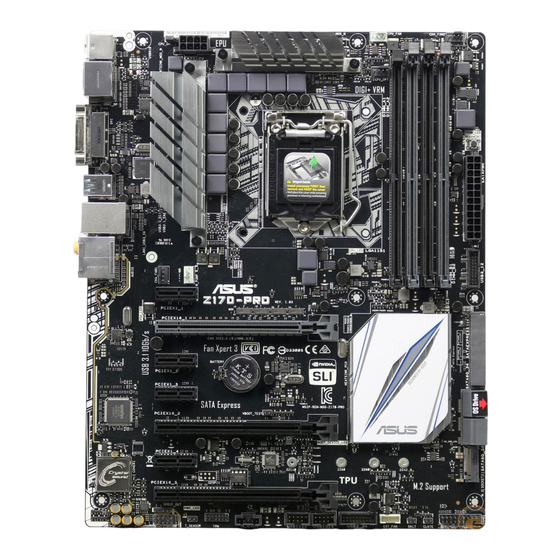
Page 22: Motherboard Layout
1.2.2 Motherboard layout Refer to 1.2.9 Internal Connectors and 2.2.1 Rear I/O connection for more information about rear panel connectors and internal connectors. Chapter 1: Product Introduction... - Page 23 14. TPM connector (14-1 pin TPM) 1-31 15. T_Sensor connector (2-pin T_SENSOR) 1-24 16. Front panel audio connector (10-1 pin AAFP) 1-25 17. Digital audio connector (4-1 pin SPDIF_OUT) 1-24 18. CPU Over Voltage jumper (3-pin CPU_OV) 1-21 ASUS Z170-PRO Series...
-
Page 24: Central Processing Unit (Cpu)
Contact your retailer immediately if the PnP cap is missing, or if you see any damage to the PnP cap/socket contacts/motherboard components. ASUS will shoulder the cost of repair only if the damage is shipment/ transit-related. -
Page 25: System Memory
The motherboard comes with four (4) Double Data Rate 4 (DDR4) Dual Inline Memory Modules (DIMM) slots. A DDR4 module is notched differently from a DDR, DDR2, or DDR3 module. DO NOT install a DDR, DDR2, or DDR3 memory module to the DDR4 slot. Recommended memory configurations ASUS Z170-PRO Series... - Page 26 Memory configurations the DIMM sockets. excess memory from the higher-sized channel is then mapped for single-channel operation. ® CPU spec, DIMM voltage below 1.65 V is recommended to protect the CPU. ® OS, when you install 4GB or more memory on the motherboard, the actual usable memory for the OS can be about 3GB or less.
- Page 27 Z170-PRO Motherboard Qualified Vendors Lists (QVL) DDR4 3866 (O.C.) MHz capability Vendors Part No. Size SS/DS Chip Chip NO. Timing Voltage DIMM socket Brand support (Optional) CORSAIR 16GB(4GB*4) Samsung K4A4G085WD 1.35V ver. 4.23 DDR4 3800 (O.C.) MHz capability Vendors Part No.
- Page 28 DDR4 3466 (O.C.) MHz capability Vendors Part No. Size SS/DS Chip Chip NO. Timing Voltage DIMM socket Brand support (Optional) G.SKILL F4-3466C16D-8GRK 8GB(4GB*2) Samsung K4A4G085WD 16-18-18-38 1.35V G.SKILL F4-3466C16D-8GTZ 8GB(4GB*2) Samsung K4A4G085WD 16-18-18-38 1.35V G.SKILL F4-3466C16D-8GVK 8GB(4GB*2) Samsung K4A4G085WD 16-18-18-38 1.35V G.SKILL F4-3466C16Q-16GRK...
- Page 29 32GB(8GB*4) Samsung K4A4G085WD 16-16-16-36 1.35V G.SKILL F4-3200C16Q-64GRK 64GB(16GB*4) Samsung 16-18-18-38 1.35V G.SKILL F4-3000C16Q-64GTZ 64GB(16GB*4) Samsung 16-18-18-38 1.35V G.SKILL F4-3200C16Q-64GVK 64GB(16GB*4) Samsung 16-18-18-38 1.35V AVEXIR AVD4U32001604G-4BZ1 16GB(4GB*4) SK Hynix H5AN4G8NMFR 16-18-18-36 1.35V (continued on the next page) ASUS Z170-PRO Series 1-11...
- Page 30 DDR4 3200 (O.C.) MHz capability Vendors Part No. Size Chip Chip NO. Timing Voltage DIMM socket Brand support (Optional) AVEXIR AVD4U32001604G-4CIR 16GB(4GB*4) 16-18-18-36 1.35V CORSAIR CMD16GX4M4B3200C16 16GB(4GB*4) 16-18-18-36 1.35V CORSAIR CMK32GX4M2B3200C16 32GB(16GB*2) Samsung 16-18-18-36 1.35V GEIL GPR416GB3200C15QC 16GB(4GB*4) 15-15-15-35 1.35V Kingston HX432C16PB2K4/16 16GB(4GB*4)
- Page 31 15-17-17-35 (Ver4.23)(XMP) (8GB*4) CORSAIR CMD32GX4M4A2666C15 32GB 15-17-17-35 (8GB*4) CORSAIR CMD32GX4M4A2666C16 32GB 16-18-18-35 (Ver4.23)(XMP) (8GB*4) CORSAIR CMK16GX4M4A2666C15 16GB 15-17-17-35 (Ver4.23)(XMP) (4GB*4) CORSAIR CMK16GX4M4A2666C15 16GB 15-17-17-35 (4GB*4) CORSAIR CMK16GX4M4A2666C16 16GB 16-18-18-35 (Ver4.23)(XMP) (4GB*4) (continued on the next page) ASUS Z170-PRO Series 1-13...
- Page 32 DDR4 2666 (O.C.) MHz capability Vendors Part No. Size SS/DS Chip Chip NO. Timing Voltage DIMM socket Brand support (Optional) CORSAIR CMK16GX4M4A2666C16 16GB 16-18-18-35 (4GB*4) CORSAIR CMK32GX4M4A2666C15 32GB 15-17-17-35 (Ver4.23)(XMP) (8GB*4) CORSAIR CMK32GX4M4A2666C15 32GB 15-17-17-35 (8GB*4) CORSAIR CMK32GX4M4A2666C16 32GB 16-16-18-35 (8GB*4) CORSAIR CMK32GX4M4A2666C16R...
- Page 33 PUD42133C154G2VS SK Hynix H5AN4GBNMFRTFC 15-15-15-36 (4GB*2) Panram PUD42133C154GNJK 15-15-15-36 Panram PUD42133C158G2VS 16GB SK Hynix H5AN4GBNMFRTFC 15-15-15-36 (8GB*2) Panram PUD42133C158GNJK 15-15-15-36 Samsung M378A1G43DB0-CPB Samsung K4A4G085WD 15-15-15-36 SanMax SMD-4G28HP-21P SK Hynix H5AN4G8NMFRTFC 15-15-15-37 (continued on the next page) ASUS Z170-PRO Series 1-15...
- Page 34 DDR4 2133 (O.C.) MHz capability Vendors Part No. Size SS/DS Chip Chip NO. Timing Voltage DIMM socket Brand support (Optional) SanMax SMD-8G28HP-21P SK Hynix H5AN4G8NMFRTFC 15-15-15-37 SK Hynix HMA82GU6MFR8N-TF 16GB SK Hynix H5AN8G8NMFRTFC 15-15-15-36 SUPER FBU2B008GM Micron 15-15-15-36 TALENT Team TED44GM2133C15ABK SK Hynix H5AN4G8NMFRTFC...
-
Page 35: Expansion Slots
Slot No. Slot Description PCIE 2.0 x1_1 slot PCIE 3.0/2.0 x16_1 slot PCIE 2.0 x1_2 slot PCIE 2.0 x1_3 slot PCIE 3.0/2.0 x16_2 slot PCIE 2.0 x1_4 slot PCIE 3.0/2.0 x16_3 slot ASUS Z170-PRO Series 1-17... - Page 36 PCI Express 3.0 operating mode VGA configuration PCIe 3.0/2.0 x16_1 PCIe 3.0/2.0 x16_2 x16 (single VGA Single VGA/PCIe card recommended) Dual VGA/PCIe card mode. using multiple graphics cards for better thermal environment. IRQ assignments for this motherboard PCIe x16_1 shared PCIe x16_2 shared PCIe x16_3...
-
Page 37: Onboard Buttons And Switches
5–10 seconds. to boot and load the BIOS default settings. A message will appear during POST reminding you that the BIOS has been restored to its default settings. www.asus.com after using the MemOK! function. ASUS Z170-PRO Series... -
Page 38: Jumpers
1.2.7 Jumpers Clear RTC RAM (2-pin CLRTC) clear the CMOS memory of date, and system setup parameters by erasing the CMOS RTC RAM data. The onboard button cell battery powers the RAM data in CMOS, which include system setup information such as system passwords. To erase the RTC RAM: Turn OFF the computer and unplug the power cord. - Page 39 CPU. To gain more CPU voltage setting, insert the jumper to pins 2-3. To go back to its default CPU voltage setting, insert the jumper to pins 1-2. ASUS Z170-PRO Series 1-21...
-
Page 40: Onboard Leds
1.2.8 Onboard LEDs POST State LEDs The POST State LEDs provide the status of these key components during POST (Power-On-Self Test): CPU, memory modules, VGA card, and hard disk drives. If an error is found, the critical component’s LED stays lit up until the problem is solved. Power LED (PWR_LED) This LED lights up when the system is on. -
Page 41: Internal Connectors
Mode]. Refer to section 3.6.5 PCH Storage Configuration for details. 5.1 RAID configurations or the manual bundled in the motherboard support DVD. be activated. To use an M.2 SATA device, refer to section 3.6.8 Onboard Devices Configuration regarding the BIOS switch. devices. ASUS Z170-PRO Series 1-23... - Page 42 T_Sensor connector (2-pin T_SENSOR) This connector is for the thermistor cable that allows you to monitor the temperature of your motherboard’s critical components and connected devices. The thermistor cable is purchased separately. Digital audio connector (4-1 pin SPDIF_OUT) This connector is for an additional Sony/Philips Digital Interface (S/PDIF) port. Connect the S/PDIF Out module cable to this connector, then install the module to a slot opening at the back of the system chassis.
- Page 43 This connector is for the add-on Thunderbolt I/O card that supports Intel’s Thunderbolt Technology, allowing you to connect up to six Thunderbolt-enabled devices and a The add-on Thunderbolt I/O card and Thunderbolt cables are purchased separately. ASUS Z170-PRO Series 1-25...
- Page 44 USB 3.0 connectors (20-1 pin USB3_12, USB3_34) These connectors allow you to connect a USB 3.0 module for additional USB 3.0 front USB 3.0 including faster data transfer speeds of up to 5 Gb/s, faster charging time for USB 2.0. The USB 3.0 module is purchased separately.
- Page 45 These connectors are for USB 2.0 ports. Connect the USB module cable to any of these connectors, then install the module to a slot opening at the back of the system 48 Mb/s connection speed. motherboard! The USB 2.0 module is purchased separately. ASUS Z170-PRO Series 1-27...
- Page 46 CPU, water pump, CPU optional, extension, and chassis fan connectors (4-pin CPU_FAN; 4-pin W_PUMP; 4-pin CPU_OPT; 5-pin EXT_FAN; 4-pin CHA_FAN1-2) Connect the fan cables to the fan connectors on the motherboard, ensuring that the black wire of each cable matches the ground pin of the connector. inside the system may damage the motherboard components.
- Page 47 The system may become unstable or may not boot up if the power is inadequate. 1000W power or above to ensure the system stability. refer to the Recommended Power Supply Wattage Calculator at http://support.asus. com/PowerSupplyCalculator/PSCalculator.aspx?SLanguage=en-us for details. ASUS Z170-PRO Series...
- Page 48 System panel connector (20-5 pin PANEL) This connector supports several chassis-mounted functions. The 2-pin or 3-1 pin connector is for the system power LED. Connect the chassis power LED cable to this connector. The system power LED lights up when you turn on the system power, and blinks when the system is in sleep mode.
- Page 49 Connect the button cable that supports DirectKey, from the chassis to this connector on the motherboard. Ensure that your chassis comes with the extra button cable that supports the DirectKey feature. Refer to the technical documentation that came with the chassis for details. ASUS Z170-PRO Series 1-31...
- Page 50 M.2 socket 3 This socket allows you to install an M.2 (NGFF) SSD module. be activated. To use an M.2 SATA device, refer to section 3.6.7 Onboard Device Configuration regarding the BIOS switch. ® Desktop Responsiveness technologies with PCIe M.2 device, ensure to set up the Windows ®...
-
Page 51: Chapter 2: Basic Installation
The diagrams in this section are for reference only. The motherboard layout may vary with models, but the installation steps are the same for all models. Install the ASUS Q-Shield to the chassis rear I/O panel. Place the motherboard into the chassis, ensuring that its rear I/O ports are aligned to the chassis’... - Page 52 Place nine (9) screws into the holes indicated by circles to secure the motherboard to the chassis. DO NOT overtighten the screws! Doing so can damage the motherboard. Chapter 2: Basic Installation...
-
Page 53: Cpu Installation
Ensure that you install the correct CPU designed for LGA1151 socket only. DO NOT install a CPU designed for LGA1155 and LGA1156 sockets on the LGA1151 socket. Top of CPU Installation Tool Top of CPU Bottom of CPU Installation Tool Bottom of CPU Installation Tool Bottom of CPU Bottom of CPU ASUS Z170-PRO Series... - Page 54 Top of CPU Top of CPU Installation Tool Top of CPU Top of CPU Installation Tool PnP cap ® LGA1151 socket. on the motherboard. the CPU Installation Tool. picking up the CPU Installation Tool. Tool to prevent CPU damage. incorrect CPU orientation/placement, or other damages resulting from negligence by the user.
-
Page 55: Cpu Heatsink And Fan Assembly Installation
2.1.3 CPU heatsink and fan assembly installation Apply the Thermal Interface Material to the CPU heatsink and CPU before you install the heatsink and fan, if necessary. To install the CPU heatsink and fan assembly ASUS Z170-PRO Series... - Page 56 To uninstall the CPU heatsink and fan assembly Chapter 2: Basic Installation...
-
Page 57: Dimm Installation
2.1.4 DIMM installation To remove a DIMM ASUS Z170-PRO Series... -
Page 58: Atx Power Connection
2.1.5 ATX Power connection Chapter 2: Basic Installation... -
Page 59: Sata Device Connection
2.1.6 SATA device connection ASUS Z170-PRO Series... -
Page 60: Front I/O Connector
2.1.7 Front I/O Connector To install ASUS Q-Connector To install USB 2.0 connector To install front panel audio connector AAFP USB 2.0 To install USB 3.0 connector USB 3.0 Chapter 2: Basic Installation 2-10... -
Page 61: Expansion Card Installation
2.1.8 Expansion Card installation To install PCIe x16 cards To install PCIe x1 cards ASUS Z170-PRO Series 2-11... -
Page 62: Motherboard Rear And Audio Connections
Motherboard rear and audio connections 2.2.1 Rear I/O connection Rear panel connectors USB 2.0 port 9 and 10 HDMI 1.4 port DisplayPort USB Type-C port EC1 (supports USB 3.1 Boost) DVI port USB 3.0 port 5 and 6 (supports USB 3.1 Boost) USB 3.1 ports EA2 (supports USB Optical S/PDIF OUT port... - Page 63 Line In Line In Side Speaker Out Lime Line Out Front Speaker Out Front Speaker Out Front Speaker Out Pink Mic In Mic In Mic In Mic In Orange – – Center/Sub Center/Sub woofer woofer Black – ASUS Z170-PRO Series 2-13...
-
Page 64: Audio I/O Connections
2.2.2 Audio I/O connections Audio I/O ports Connect to Headphone and Mic Connect to Stereo Speakers Connect to 2.1 channel Speakers Chapter 2: Basic Installation 2-14... - Page 65 Connect to 4.1 channel Speakers Connect to 5.1 channel Speakers Connect to 7.1 channel Speakers ASUS Z170-PRO Series 2-15...
-
Page 66: Starting Up For The First Time
Starting up for the first time After making all the connections, replace the system case cover. Ensure that all switches are off. Connect the power cord to the power connector at the back of the system chassis. Connect the power cord to a power outlet that is equipped with a surge protector. Monitor System power After applying power, the system power LED on the system front panel case lights up. -
Page 67: Chapter 3: Bios Setup
Chapter 3: BIOS Setup BIOS Setup Knowing BIOS DO NOT change the default BIOS settings We strongly recommend that you change the BIOS settings only with the help of a trained service personnel Z170P.CAP ASUS Z170-PRO Series... -
Page 68: Bios Setup Program
BIOS setup program Entering BIOS at startup Entering BIOS Setup after POST Load Optimized Defaults Exit <F5> 3.10 Exit Menu 1.2.6 Onboard buttons and switches BIOS menu screen EZ Mode Advanced Mode Exit Exit/Advanced Mode Chapter 3: BIOS Setup... -
Page 69: Ez Mode
Displays the CPU Fan’s speed. Click the button to manually tune the fans Click to go to Advanced mode Loads optimized Search on the FAQ default settings Click to display boot devices Selects the boot device priority ASUS Z170-PRO Series... -
Page 70: Advanced Mode
3.2.2 Advanced Mode Advanced Mode Configuration fields Quick Note (F9) Pop-up Menu Scroll bar Menu bar Language MyFavorite(F3) Qfan Control(F6) EZ Tuning Wizard(F11) Hot Keys Go back to EZ Mode Last modified settings Menu items General help Sub-menu item Search on the FAQ Displays the CPU temperature, CPU, and memory voltage output Chapter 3: BIOS Setup... - Page 71 Menu bar My Favorites Main Ai Tweaker Advanced Monitor Boot Tool Exit Menu items Main Submenu items Language My Favorites (F3) 3.3 My Favorites Q-Fan Control (F6) 3.2.3 QFan Control EZ Tuning Wizard (F11) 3.2.4 EZ Tuning Wizard ASUS Z170-PRO Series...
- Page 72 Search on FAQ Quick Note (F9) Hot keys Scroll bar General help Configuration fields Last Modified button Chapter 3: BIOS Setup...
-
Page 73: Qfan Control
Click to activate DC Mode configured PWM Mode Select a profile to apply to Click to apply the fan setting your fans Click to undo the Click to go back to main menu changes Select to manually configure your fans ASUS Z170-PRO Series... - Page 74 Configuring fans manually Manual Speed points Select to manually configure your fans Apply Exit (ESC) Chapter 3: BIOS Setup...
- Page 75 3.2.4 EZ Tuning Wizard OC setup RAID setup OC Tuning Next Daily Computing Gaming/Media Editing, Next ASUS Z170-PRO Series...
- Page 76 BOX cooler, Tower cooler, Water cooler, I’m not sure, Next Next Creating RAID RAID Next ® PCIE SATA Next Chapter 3: BIOS Setup 3-10...
- Page 77 Easy Backup Super Speed Next Next Easy Backup (RAID1) Easy Backup (RAID10) Next Super Speed (RAID0) Super Speed (RAID5) Next ASUS Z170-PRO Series 3-11...
-
Page 78: My Favorites
My Favorites Chapter 3: BIOS Setup 3-12... - Page 79 Adding items to My Favorites Main menu panel Selected shortcut items Submenu panel Delete all favorite items Recover to default favorite items Exit (ESC) ASUS Z170-PRO Series 3-13...
-
Page 80: Main Menu
Main menu Security 1.2.6 Onboard buttons and switches [Not Installed] [Installed] Chapter 3: BIOS Setup 3-14... - Page 81 Administrator Password Create New Password To change an administrator password: Administrator Password Enter Current Password Create New Password Administrator Password [Not Installed]. User Password [Not Installed]. [Installed.] To set a user password: User Password Create New Password ASUS Z170-PRO Series 3-15...
-
Page 82: Ai Tweaker Menu
To change a user password: User Password Enter Current Password Create New Password User Password [Not Installed]. Ai Tweaker menu Chapter 3: BIOS Setup 3-16... - Page 83 Ai Overclock Tuner [Auto] [Manual] BCLK Frequency [100.00] ASUS MultiCore Enhancement [Auto] CPU Core Ratio [Auto] [Synch All Cores] 1-Core Ratio Limit [Auto] [Auto] [Per Core] 1-Core Ratio Limit [Auto] [Auto] ASUS Z170-PRO Series...
- Page 84 2-Core Ratio Limit [Auto] [Auto] 3-Core Ratio Limit [Auto] [Auto] 4-Core Ratio Limit [Auto] [Auto] [Auto] DRAM Odd Ratio Mode [Enabled] DRAM Frequency [Auto] TPU [Keep Current Settings] [TPU II]. EPU Power Saving Mode [Disabled] CPU SVID Support [Auto] Chapter 3: BIOS Setup 3-18...
- Page 85 DRAM WRITE Recovery Time [Auto] DRAM READ to PRE Time [Auto] DRAM FOUR ACT WIN Time [Auto] DRAM WRITE to READ Delay [Auto] DRAM WRITE to READ Delay L [Auto] DRAM WRITE to READ Delay S [Auto] ASUS Z170-PRO Series 3-19...
- Page 86 DRAM CKE Minimum Pulse Width [Auto] DRAM Write Latency [Auto] Skew Control ODT RTT WR (CHA) [Auto] ODT RTT PARK (CHA) [Auto] ODT RTT NOM (CHA) [Auto] ODT RTT WR (CHB) [Auto] ODT RTT PARK (CHB) [Auto] ODT RTT NOM (CHB) [Auto] ODT_READ_DURATION [Auto] ODT_READ_DELAY [Auto] ODT_WRITE_DURATION [Auto]...
- Page 87 DRAM RTL (CHB DIMM0 Rank0) [Auto] DRAM RTL (CHB DIMM0 Rank1) [Auto] DRAM RTL (CHB DIMM1 Rank0) [Auto] DRAM RTL (CHB DIMM1 Rank1) [Auto] DRAM IOL (CHA DIMM0 Rank0) [Auto] DRAM IOL (CHA DIMM0 Rank1) [Auto] ASUS Z170-PRO Series 3-21...
- Page 88 DRAM IOL (CHA DIMM1 Rank0) [Auto] DRAM IOL (CHA DIMM1 Rank1) [Auto] DRAM IOL (CHB DIMM0 Rank0) [Auto] DRAM IOL (CHB DIMM0 Rank1) [Auto] DRAM IOL (CHB DIMM1 Rank0) [Auto] DRAM IOL (CHB DIMM1 Rank1) [Auto] IO Latency offset CHA IO_Latency_offset CHB IO_Latency_offset IO Latency RFR delay CHA RFR delay...
- Page 89 [Auto] tWRRD_dd[Auto] TWRPRE [Auto] TRDPRE [Auto] tREFIX9 [Auto] OREF_RI[Auto] Misc. MRC Fast Boot [Auto] DRAM CLK Period [Auto] Memory Scrambler [Enabled] Channel A DIMM Control [Enable Both DIMMs] Channel B DIMM Control [Enable Both DIMMs] ASUS Z170-PRO Series 3-23...
- Page 90 MCH Full Check [Auto] DLLBwEn [Auto] DIGI+ VRM CPU Load-line Calibration [Auto] ® CPU Current Capability [Auto] CPU VRM Switching Frequency [Auto] Manual [Manual] Fixed CPU VRM Switching Frequency (KHz) [300] Chapter 3: BIOS Setup 3-24...
- Page 91 Auto VRM Spread Spectrum [Auto] CPU Power Duty Control [T.Probe] CPU Power Phase Control [Auto] CPU Graphics Load-line Calibration [Auto] CPU Graphics Current Capability [Auto] CPU Graphics Switching Frequency [Auto] ASUS Z170-PRO Series 3-25...
- Page 92 CPU Graphics Switching Frequency [Manual] Fixed CPU Graphics Switching Frequency (KHz) [300] CPU Graphics Power Phase Control [Auto] Boot Voltages CPU Core/Cache Boot Voltage [Auto] DMI Boot Voltage [Auto] CPU System Agent Boot Voltage [Auto] CPU VCCIO Boot Voltage [Auto] CPU Standby Boot Voltage [Auto] Internal CPU Power Management Intel(R) SpeedStep(tm) [Auto]...
- Page 93 Short Duration Package Power Limit [Auto] IA AC Load Line [Auto] IA DC Load Line [Auto] Tweaker’s Paradise FCLK Frequency for Early Power On [Auto] Initial BCLK Frequency [Auto] BCLK Amplitude [Auto] BCLK Slew Rate [Auto] BCLK Spread Spectrum [Auto] ASUS Z170-PRO Series...
- Page 94 BCLK Frequency Slew Rate [Auto] VPPDDR Voltage [Auto] DMI Voltage [Auto] Internal PLL Voltage [Auto] CPU Core/Cache Current Limit Max. [Auto] CPU Graphics Current Limit Max. [Auto] Min. CPU Cache Ratio [Auto] Max. CPU Cache Ratio [Auto] Max. CPU Graphics Ratio [Auto] Extreme Over-voltage [Disabled] CPU Core/Cache Voltage [Auto] Chapter 3: BIOS Setup...
- Page 95 CPU Core Voltage Offset [Auto] [Adaptive Mode] Offset Mode Sign [-] Additional Turbo Mode CPU Core Voltage [Auto] Offset Voltage [Auto] DRAM Voltage [Auto] CPU VCCIO Voltage [Auto] CPU System Agent Voltage [Auto] CPU Graphics Voltage Mode [Auto] [Manual Mode] ASUS Z170-PRO Series 3-29...
- Page 96 CPU Graphics Voltage Override [Auto] [Offset Mode] Offset Mode Sign [+] CPU Graphics Voltage Offset [Auto] PCH Core Voltage [Auto] CPU Standby Voltage [Auto] DRAM REF Voltage Control DRAM CTRL REF Voltage on CHA/CHB [Auto] DRAM DATA REF Voltage on CHA DIMM0 Rank0 BL0-7 [Auto] DRAM DATA REF Voltage on CHA DIMM0 Rank1 BL0-7 [Auto] DRAM DATA REF Voltage on CHA DIMM1 Rank0 BL0-7 [Auto] DRAM DATA REF Voltage on CHA DIMM1 Rank1 BL0-7 [Auto]...
-
Page 97: Advanced Menu
DRAM DATA REF Voltage on CHB DIMM1 Rank0 BL0-7 [Auto] DRAM DATA REF Voltage on CHB DIMM1 Rank1 BL0-7 [Auto] Advanced menu ASUS Z170-PRO Series 3-31... - Page 98 3.6.1 CPU Configuration Active Processor Cores [All] Intel Virtualization Technology [Enabled] [Enabled] Hardware Prefetcher [Enabled] Chapter 3: BIOS Setup 3-32...
- Page 99 Adjacent Cache Line Prefetcher [Enabled] Boot Performance Mode [Auto] CPU Power Management Configuration Intel SpeedStep(tm) [Auto] Turbo Mode [Enabled] CPU C-States [Auto] [Enabled] Enhanced C-States [Disabled] CPU C3 Report [Enabled] CPU C6 Report [Enabled] ASUS Z170-PRO Series 3-33...
- Page 100 CPU C7 Report [CPU C7s] CPU C8 Report [Enabled] Package C State Limit [Auto] CFG Lock [Disabled] 3.6.2 Platform Misc Configuration PCIE Native Power Management [Disabled] [Enabled] Native ASPM [Disabled] ® Chapter 3: BIOS Setup 3-34...
- Page 101 PCH - PCI Express DMI Link ASPM Control [Disabled] ASPM Support [Disabled] SA - PCI Express DMI Link ASPM Control [Disabled] PEG - ASPM [Disabled] 3.6.3 System Agent (SA) Configuration VT-d [Disabled] Graphics Configuration ASUS Z170-PRO Series 3-35...
- Page 102 Primary Display [Auto] iGPU Multi-Monitor [Disabled] RC6(Render standby) [Enabled] DVMT Pre-Allocated [32M] DMI/OPI Configuration DMI Max Link Speed [Auto] [Enabled] PEG Port Configuration PCIEx16_1 Link Speed [Auto] PCIEx16_2 Link Speed [Auto] 3.6.4 PCH Configuration Chapter 3: BIOS Setup 3-36...
- Page 103 PCI Express Configuration PCIe Speed [Auto] 3.6.5 PCH Storage Configuration Not Present Hyper kit Mode [Disabled] SATA Controller(s) [Enabled] ASUS Z170-PRO Series...
- Page 104 SATA Mode Selection [AHCI] [RAID] M.2 PCIE Storage RAID Support [Disabled] SATA Express PCIE Storage RAID Support [Disabled] PCIEX16_3 PCIE Storage RAID Support [Disabled] SMART Self Test [On] Aggressive LPM Support [Disabled] SATA6G_1(Gray) - SATA6G_6(Gray) SATA6G_1(Gray) - SATA6G_6(Gray) [Enabled] Hot Plug [Disabled] AHCI Chapter 3: BIOS Setup 3-38...
- Page 105 3.6.6 USB Configuration The Mass Storage Devices None Legacy USB Support [Enabled] XHCI Hand-off [Disabled] USB Keyboard and Mouse Simulator [Enabled] USB Single Port Control 1.2.2 Motherboard layout ASUS Z170-PRO Series 3-39...
- Page 106 3.6.7 Network Stack Configuration Network stack [Disable] [Enabled] Ipv4/Ipv6 PXE Support [Enabled] 3.6.8 Onboard Devices Configuration Chapter 3: BIOS Setup 3-40...
- Page 107 SPDIF Out Type [SPDIF] DVI Port Audio [Disabled] Audio LED Lighting [Breathing Mode] [Still Mode] [Breathing Mode] S3/S4/S5 Audio LED [Disabled] PCI-EX16_3 Bandwidth [Auto] M.2 and SATA Express Mode Configuration [SATA Express] Intel LAN Controller [Enabled] ASUS Z170-PRO Series 3-41...
- Page 108 [Enabled] Intel PXE Option ROM [Disabled] ® Intel USB 3.1 Controller [Enabled] ® USB Type C Power Switch [Auto] 3.6.9 APM Configuration ErP Ready [Disabled] [Enabled] Restore AC Power Loss [Power Off] Power On By PCI-E/PCI [Disabled] Chapter 3: BIOS Setup 3-42...
-
Page 109: Hdd/Ssd Smart Information
Power On By RTC [Disabled] 3.6.10 HDD/SSD SMART Information ASUS Z170-PRO Series 3-43... - Page 110 3.6.11 Intel(R) Thunderbolt Configuration Intel Thunderbolt Technology [Enabled] ® ThunderBolt Boot Support [Disabled] Thunderbolt USB Support [Disabled] Security Level [Unique ID] Wake From Thunderbolt Devices [On] AIC support [On] AR AIC Support [Off] Chapter 3: BIOS Setup 3-44...
- Page 111 GPIO3 Force Pwr [Off] Wait time in ms after applying Force Pwr [200] Thunderbolt PCIe Cache-line Size [32] SMI/Notify Support [On] SwSMI Support [On] Notify Support [On] MSI enabled in FADT [Enabled] Enable CLK REQ [Disabled] Enable ASPM [Disabled] ASUS Z170-PRO Series 3-45...
- Page 112 Enable LTR [Disabled] Native OS Hot Plug [Off] GPIO filter [Enabled] _RMV Method return value [0] Ignore Thunderbolt Option Rom [On] Thunderbolt SwSMI Delay [0] TBT Device IO resource Support [Off] Reserved Mem per phy slot [32] Reserved PMem per phy slot [32] Chapter 3: BIOS Setup 3-46...
-
Page 113: Monitor Menu
Temperature / EXT_SENSOR1-3 Temperature [xxx°C/xxx°F] [Ignore] CPU Fan Speed, CPU Optional Fan, Water Pump Speed, Chassis Fan 1-2 Speed, EXT Fan 1-3 [xxxx RPM] or [Ignore] / [N/A] [Ignore] CPU Core Voltage, 3.3V Voltage, 5V Voltage, 12V Voltage [Ignore] ASUS Z170-PRO Series... - Page 114 Qfan Configuration Qfan Tuning CPU Q-Fan Control [Auto] CPU Fan Step Up [0 sec] CPU Fan Step Down [0 sec] CPU Fan Speed Lower Limit [200 RPM] CPU Fan Profile [Standard] [Manual] CPU Upper Temperature [70] CPU Fan Max. Duty Cycle (%) [100] CPU Middle Temperature [25] Chapter 3: BIOS Setup 3-48...
- Page 115 Chassis Fan 1-2 Q-Fan Control [DC Mode] Chassis Fan 1-2 Q-Fan Source [CPU] Chassis Fan 1-2 Step Up [0 sec] Chassis Fan 1-2 Step Down [0 sec] Chassis Fan 1-2 Fan Speed Low Limit [200 RPM] Chassis Fan 1-2 Profile [Standard] ASUS Z170-PRO Series 3-49...
- Page 116 Chassis Fan 1-2 Lower Temperature [40] Chassis Fan 1-2 Min. Duty Cycle(%) [60] Allow Fan Stop [Disabled] ASUS FAN EXTENSION CARD is required to configure these items Extension Fan 1-3 Q-Fan Control [DC Mode] Extension Fan 1-3 Q-Fan Source [CPU]...
- Page 117 Extension Fan 1-3 Max. Duty Cycle (%) [100] Extension Fan 1-3 Middle Temperature [45] Extension Fan 1-3 Middle. Duty Cycle (%) [60] Extension Fan 1-3 Lower Temperature [40] Extension Fan 1-3 Min. Duty Cycle(%) [60] Allow Fan Stop [Disabled] Water Pump Control [Disabled] ASUS Z170-PRO Series 3-51...
- Page 118 [DC mode] [PWM mode]. Water Pump Upper Temperature [70] Water Pump Max. Duty Cycle (%) [100] Water Pump Middle Temperature [25] Water Pump Middle. Duty Cycle (%) [100] Water Pump Lower Temperature [20] Water Pump Min. Duty Cycle(%) [100] Anti Surge Support [On] Chapter 3: BIOS Setup 3-52...
-
Page 119: Boot Menu
Boot menu Fast Boot [Enabled] [Enabled] Next Boot after AC Power Loss [Normal Boot] DirectKey (DRCT) [Enabled] Boot Logo Display [Auto] [Auto] [Full Screen] ASUS Z170-PRO Series 3-53... - Page 120 Post Delay Time [3 sec] [Disabled] Post Report [5 sec] Boot up NumLock State [Enabled] Above 4G Decoding [Disabled] Wait For ‘F1’ If Error [Enabled] Option ROM Messages [Enabled] Interrupt 19 Capture [Disabled] Setup Mode [EZ Mode] Chapter 3: BIOS Setup 3-54...
- Page 121 Boot from Network Devices [Legacy only] Boot from Storage Devices [Legacy only] Boot from PCI-E/PCI Expansion Devices [Legacy only] Secure Boot ® OS Type [Windows UEFI mode] ® ® ® ® ® ® Key Management Clear Secure Boot keys ASUS Z170-PRO Series 3-55...
- Page 122 Save Secure Boot Keys PK Management Set New Key Delete Key KEK Management ® Set New Key Append Key Delete Key DB Management Set New Key Append Key Delete Key Chapter 3: BIOS Setup 3-56...
- Page 123 DBX Management Set New Key Append Key Delete Key Boot Option Priorities ® ® Boot Override ASUS Z170-PRO Series...
-
Page 124: Tool Menu
Tool menu Setup Animator [Disabled] 3.9.1 ASUS EZ Flash 3 Utility 3.11.2 ASUS EZ Flash 3 3.9.2 Secure Erase Advanced > SATA Configuration > AHCI. Tool > Secure Erase Chapter 3: BIOS Setup 3-58... - Page 125 Displays the available SSDs Status definition: Frozen. Locked. ASUS Z170-PRO Series 3-59...
- Page 126 3.9.3 ASUS Overclocking Profile Load from Profile Profile Name Save to Profile Load/Save Profile from/to USB Drive Chapter 3: BIOS Setup 3-60...
-
Page 127: Asus Spd Information
3.9.4 ASUS SPD Information 3.9.5 Graphics Card Information GPU Post Bus Interface ASUS Z170-PRO Series 3-61... -
Page 128: Exit Menu
3.10 Exit menu Load Optimized Defaults Save Changes & Reset Discard Changes & Exit Launch EFI Shell from USB drives Chapter 3: BIOS Setup 3-62... -
Page 129: Updating Bios
3.11 Updating BIOS ® 3.11.1 EZ Update ® 4.4.3 EZ Update ASUS Z170-PRO Series 3-63... -
Page 130: Asus Ez Flash 3
3.11.2 ASUS EZ Flash 3 To update the BIOS by USB: ASUS EZ Flash Utility by USB. Chapter 3: BIOS Setup 3-64... - Page 131 3.10 Exit Menu To update the BIOS by Internet: ASUS EZ Flash Utility by Internet. 3.10 Exit Menu ASUS Z170-PRO Series 3-65...
-
Page 132: Asus Crashfree Bios 3
3.11.3 ASUS CrashFree BIOS 3 Recovering the BIOS To recover the BIOS: Chapter 3: BIOS Setup 3-66... -
Page 133: Chapter 4: Software Support
Connect the USB ODD or USB storage device to your 100 series platform. Insert the ASUS support DVD into a SATA ODD on your 100 series platform. Power on your system and press F8 during POST (Power-On Self Test) to enter the boot screen. - Page 134 Select the USB ODD or USB storage device as the boot device. The USB 3.0 driver will be loaded automatically during installation startup. The “Setup is starting...” screen will show up if the USB 3.0 driver is loaded correctly. Follow the onscreen instructions to complete the Windows ®...
- Page 135 7 installation DVD. Requirement: ® 7 installation source ® 7 installation source using a third-party ISO software. the ASUS supporting DVD to your system. ® 7 installation DVD. ® 7 installation DVD into an ODD on your 100 series platform.
- Page 136 7 installation DVD ® Insert the Windows 7 installation DVD. Launch the ASUS EZ Installer located on the ASUS support DVD. ® ® 7 OS disk to USB storage device - Select Windows 7 OS disk to USB storage device then click Next.
- Page 137 - Click Yes to clear the contents on the USB storage device and create a bootable USB device. Make sure to backup contents on the USB storage device, as it will be formatted. - Once completed, click OK ASUS Z170-PRO Series...
- Page 138 ® - Select Windows 7 OS disk to ISO file then click Next. - Check I agree and then click Next. 7 installation disk then click Next. - Select the source of the Windows ® Chapter 4: Software Support...
- Page 139 The USB 3.0 driver will be loaded automatically during installation startup. The “Setup is starting...” screen will show up if the USB 3.0 driver is loaded correctly. Follow the onscreen instructions to complete the Windows ® 7 installation. ASUS Z170-PRO Series...
-
Page 140: Support Dvd Information
Ensure that you have an Administrator account before running the support DVD in your operating system. Place the Support DVD into the optical drive. In the AutoPlay Run ASSETUP.EXE. If the AutoPlay double-Click \\bin\ASSETUP.EXE to launch the ASUS motherboard support DVD main menu. Chapter 4: Software Support... -
Page 141: Obtaining The Software Manuals
Click to display product related information Click to select an item to install Click to display the ASUS contact information Click to browse the file list of the suport CD Click to install the selected items 4.2.2 Obtaining the software manuals The software manuals are included in the support DVD. -
Page 142: Software Information
Most of the applications in the support DVD have wizards that will conveniently guide you application for more information. AI Suite 3 AI Suite 3 is an all-in-one interface that integrates several ASUS utilities and allows you to launch and operate these utilities simultaneously. Installing AI Suite 3 Ensure that you have an Administrator account before installing AI Suite 3 in your operating system. - Page 143 Launching AI Suite 3 ® Windows 7 OS From the Desktop, Click Start > All Programs > ASUS > AI Suite 3 > AI Suite 3. You can also launch AI Suite in Windows ® 7 by clicking or tapping area.
- Page 144 - allowing you to optimize performance settings while at the same time ensuring system stability. any of the integrated ASUS utilities. Click on the left of the menu to launch the menu bar. The AI Suite 3 screenshots in this section are for reference only and can vary depending on motherboard model.
- Page 145 The AI Suite 3 mini-menu appears on the desktop and can be conveniently accessed and the AI Suite 3. Click to expand the quick launch area or start quick launch Quick launch area Click to select the available features for AI Suite 3 mini-menu ASUS Z170-PRO Series 4-13...
-
Page 146: Ai Charger
4.4.1 Ai Charger Ai Charger allows you to fast-charge your portable BC 1.1* mobile devices on your computer’s USB port three times faster than the standard USB devices**. Launching Ai Charger on the left of the AI Suite 3 main menu, then select Ai To launch Ai Charger, click Charger. -
Page 147: Usb 3.1 Boost
Ensure to connect your USB 3.0 or 3.1 device to the USB ports that support USB 3.1 Boost. Refer to the Rear I/O connection section of your user guide for more details. UASP-supported USB devices, visit the ASUS website at www.asus.com. performance, use a USB 3.1 device. -
Page 148: Ez Update
4.4.3 EZ Update EZ Update is a utility that allows you to automatically update your motherboard’s software, drivers and BIOS easily. With this utlity, you can also manually update the BIOS and select the boot logo that displays during POST. Launching EZ Update To launch EZ Update, click on the left of the AI Suite 3 main menu, then select EZ... - Page 149 Click to go back to EZ Click to proceed the updating BIOS Update main screen and boot logo After you Click BIOS Update button, Click Flash to update the BIOS and upload the boot logo in your system. ASUS Z170-PRO Series 4-17...
-
Page 150: Push Notice
4.4.4 Push Notice This utility allows you get the detailed status of your system to your smart device. You can also send messages to your smart device using this utility. Before using this utility, ensure that you pair your computer with your smart device. For pairing information, refer to section Pairing your computer and smart device. - Page 151 Tick to select the smart device Tick to select and send alerts to your smart device Tick to send alert when the components selected are back to its normal status ASUS Z170-PRO Series 4-19...
- Page 152 Sending messages to your smart device This feature allows you to send messages to your smart device. You can also send messages via the Push Notice messaging shortcut on the lower-right corner of your screen. To do this, Click << then Click then select Tick to select the smart device...
-
Page 153: System Information
AI Suite 3 main menu, then select System Information. Viewing the motherboard information Click the MB tab to view the motherboard’s information. Viewing the CPU information Click the CPU tab to view the processor’s information. ASUS Z170-PRO Series 4-21... - Page 154 Viewing the SPD information Click the SPD tab to view the memory’s information. Chapter 4: Software Support 4-22...
-
Page 155: Audio Configurations
HD Audio Manager with DTS Studio Sound Windows ® 8.1 / Windows ® Configuration option tabs (vary with the audio devices connected) Advanced settings Set default device button Control settings panel Analog and digital connector status ASUS Z170-PRO Series 4-23... - Page 156 Selecting an audio output Realtek HD Audio Manager allows you to select the type of audio output depending on the output device that you are using. Insert the audio device’s jack to the Line Out (lime) port. If the audio device’s jack is already inserted to the corresponding port, Click on the Realtek HD Audio Manager.
-
Page 157: Chapter 5: Raid Support
Use a minimum of three identical hard disk drives for this setup. RAID 10 is data striping and data mirroring combined without parity (redundancy data) having and three new drives for this setup. ASUS Z170-PRO Series... -
Page 158: Installing Serial Ata Hard Disks
5.1.2 Installing Serial ATA hard disks The motherboard supports Serial ATA hard disk drives. For optimal performance, install identical drives of the same model and capacity when creating a disk array. Install the SATA hard disks into the drive bays. Connect the SATA signal cables. -
Page 159: Intel ® Rapid Storage Technology Option Rom Utility
The navigation keys at the bottom of the screen allow you to move through the menus and select the menu options. The RAID BIOS setup screens shown in this section are for reference only and may not exactly match the items on your screen. ASUS Z170-PRO Series... - Page 160 Creating a RAID set From the utility main menu, select 1. Create RAID Volume and press <Enter>. The Name: Volume 0 RAID Level: aaaaaaaaaaaaaaa Disks: dssdsdsds Strip Size:aaaaaaaaaaaaaaaa Capacity:aaaaaaaaaaaaaa Sync:aaaaaaaaaa Create volume [HELP] Enter a unique volume name that has no special characters and is 16 characters or less.
- Page 161 ALL DATA ON SELECTED DISKS WILL BE LOST. Are you sure you want to create this volume? (Y/N) Press <Y> to create the RAID volume and return to the main menu, or <N> to go back to the CREATE VOLUME menu. ASUS Z170-PRO Series...
- Page 162 Deleting a RAID set Be cautious when deleting a RAID set. You will lose all data on the hard disk drives when you delete a RAID set. From the utility main menu, select 2. Delete RAID Volume and press <Enter>. The [DELETE VOLUME MENU] Name Level...
-
Page 163: Creating A Raid Driver Disk
Select 32bit or 64bit folder selected folder to the root path of your USB storage device. ® To set up a Windows UEFI operating system under RAID mode, ensure to load the UEFI driver for your optical drive. ASUS Z170-PRO Series... -
Page 164: Installing The Raid Driver During Windows Os Installation
5.2.2 Installing the RAID driver during Windows ® installation To install the RAID driver for Windows ® During the OS installation, click Load Driver to allow you to select the installation media containing the RAID driver. the optical drive, and then click Browse. Click the name of the device you’ve inserted, go to Drivers >... -
Page 165: Appendix
Consult the dealer or an experienced radio/TV technician for help. The use of shielded cables for connection of the monitor to the graphics card is required expressly approved by the party responsible for compliance could void the user’s authority to operate this equipment. ASUS Z170-PRO Series... - Page 166 IC: Canadian Compliance Statement 210 of Industry Canada. This Class B device meets all the requirements of the Canadian interference-causing equipment regulations. This device complies with Industry Canada license exempt RSS standard(s). Operation is subject to the following two conditions: (1) this device may not cause interference, and (2) this device must accept any interference, including interference that may cause undesired operation of the device.
- Page 167 ASUS Recycling/Takeback Services ASUS recycling and takeback programs come from our commitment to the highest standards for protecting our environment. We believe in providing solutions for you to be able to responsibly recycle our products, batteries, other components as well as the packaging materials.
- Page 168 Português A AsusTek Inc. declara que este dispositivo está em English AsusTek Inc. hereby declares that this device is in compliance with conformidade com os requisitos essenciais e outras disposições relevantes the essential requirements and other relevant provisions of CE Directives. das Diretivas da CE.
-
Page 169: Asus Contact Information
+1-510-739-3777 +1-510-608-4555 Web site http://www.asus.com/us/ Technical Support Support fax +1-812-284-0883 Telephone +1-812-282-2787 Online support http://www.service.asus.com/ ASUS COMPUTER GmbH (Germany and Austria) Address Harkort Str. 21-23, D-40880 Ratingen, Germany +49-2102-959911 Web site http://www.asus.com/de Online contact http://eu-rma.asus.com/sales Technical Support Telephone +49-1805-010923 Support Fax... - Page 170 Appendix...
Need help?
Do you have a question about the Z170-PRO and is the answer not in the manual?
Questions and answers