Table of Contents
Advertisement
Advertisement
Table of Contents

Related Manuals for Asus Z170M-PLUS


Summary of Contents for Asus Z170M-PLUS
- Page 1 Z170M-PLUS...
- Page 2 Product warranty or service will not be extended if: (1) the product is repaired, modified or altered, unless such repair, modification of alteration is authorized in writing by ASUS; or (2) the serial number of the product is defaced or missing.
-
Page 3: Table Of Contents
Contents Safety information ..................iv About this guide ..................iv Package contents ..................vi Z170M-PLUS specifications summary ............vi Chapter 1: Product introduction Before you proceed ..............1-1 Motherboard overview ..............1-1 Central Processing Unit (CPU) ........... 1-4 System memory ................1-7 Expansion slots ................ -
Page 4: Safety Information
Safety information Electrical safety • To prevent electrical shock hazard, disconnect the power cable from the electrical outlet before relocating the system. • When adding or removing devices to or from the system, ensure that the power cables for the devices are unplugged before the signal cables are connected. If possible, disconnect all power cables from the existing system before you add a device. -
Page 5: Conventions Used In This Guide
Refer to the following sources for additional information and for product and software updates. ASUS websites The ASUS website provides updated information on ASUS hardware and software products. Refer to the ASUS contact information. Optional documentation Your product package may include optional documentation, such as warranty flyers, that may have been added by your dealer. -
Page 6: Package Contents
Turbo Boost Technology 2.0* ® The Intel Turbo Boost Technology 2.0 support depends on the CPU types. ® ** Refer to www.asus.com for Intel® CPU support list. Intel Z170 Express Chipset Chipset ® 4 x DIMM, maximum 64 GB, DDR4 3466(O.C.)/3400(O.C.)/3333(O.C.)/3300(O. -
Page 7: Audio Features
- ASUS DIGI+ VRM - 4+2+1 phase digital power design - ASUS Enhanced DRAM Overcurrent Protection - Short circuit damage prevention - ASUS LAN Guard - ASUS Overvoltage Protection ASUS - ASUS Stainless Steel Back I/O - 3x more durable corrosion-resistant coating Unique Superb Performance Features M.2 onboard... - Page 8 ASUS Exclusive Features ASUS Unique Features - ASUS Ai Charger - ASUSAI Suite 3 - ASUS Disk Unlocker featuring 3TB + HDD support - ASUS Anti Surge EZ DIY Push Notice - Monitor your PC status with smart devices in real time...
- Page 9 Quiet Thermal Design ASUS Quiet Thermal - ASUS Fan Xpert 3 Solution - ASUS Fanless Design: PCH Heatsink & MOS Heatsink solution 1 x PS/2 keyboard port (purple) 1 x PS/2 mouse port (green) 1 x HDMI port 1 x DVI-D port...
- Page 10 Z170M-PLUS specifications summary 128 Mb Flash ROM, UEFI AMI BIOS, PnP, DMI 3.0, WfM2.0, SM BIOS 3.0, ACPI 5.0, Multi-language BIOS, ASUS EZ Flash 3, ASUS CrashFree BIOS 3, F11 EZ Tuning Wizard, F6 Qfan Control, F3 My Favorites, Quick Note, Last...
-
Page 11: Chapter 1: Product Introduction
Placement direction When installing the motherboard, place it into the chassis in the correct orientation. The edge with external ports goes to the rear part of the chassis as indicated in the image. 1.2.2 Screw holes Place six screws into the holes indicated by circles to secure the motherboard to the chassis. Do not overtighten the screws! Doing so can damage the motherboard. ASUS Z170M-PLUS... -
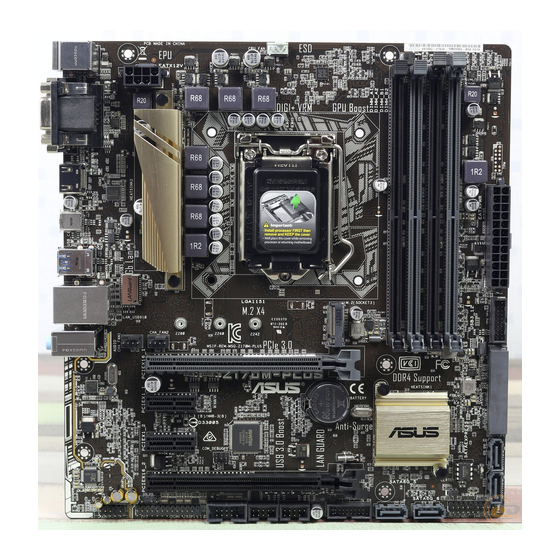
Page 12: Motherboard Layout
Place this side towards the rear of the chassis Z170M-PLUS 1.2.3 Motherboard layout 22.7cm(8.95in) KBMS CPU_FAN DIGI +VRM EATX12V HDMI 1442K LGA1151 USB_C1 USB3_78 LAN_USB_910 AUDIO CHA_FAN2 CHA_FAN1 PCIEX16_1 Z170M-PLUS Intel ® PCIEX1_1 BATTERY I219V Intel ® Z170 Super PCIEX1_2... -
Page 13: Layout Contents
4. M.2 Socket 3 1-19 5. DDR4 DIMM slots 6. Standby power LED (SB_PWR) 1-23 7. USB 3.0 connectors (20-1 pin USB3_12, USB3_34) 1-16 8. Intel Z170 Serial ATA 6.0Gb/s connectors (7-pin SATA 6G_1~6, SATA ® 1-21 EXPRESS) 9. System panel connector (20-5 pin PANEL) 1-22 10. Clear RTC RAM (2-pin CLRTC) 1-12 11. USB 2.0 connectors (10-1 pin USB1112, USB1314) 1-15 12. Serial port connectors (10-1 pin COM) 1-15 13. LPT connector (26-1 pin LPT) 1-18 14. Front panel audio connector (10-1 pin AAFP) 1-18 15. Digital audio connector (4-1 pin SPDIF_OUT) 1-20 ASUS Z170M-PLUS... -
Page 14: Central Processing Unit (Cpu)
Central Processing Unit (CPU) This motherboard comes with a surface mount LGA1151 socket designed for the 6th Generation Intel Core™ i7 / Core™ i5 / Core™ i3, Pentium and Celeron processors. ® ® ® Z170M-PLUS Z170M-PLUS CPU socket LGA1151 Unplug all power cables before installing the CPU. • Ensure that you install the correct CPU designed for the LGA1151 socket only. DO NOT install a CPU designed for LGA1150, LGA1155 and LGA1156 sockets on the LGA1151 socket. • Upon purchase of the motherboard, ensure that the PnP cap is on the socket and the socket contacts are not bent. Contact your retailer immediately if the PnP cap is missing, or if you see any damage to the PnP cap/socket contacts/motherboard components. -
Page 15: Installing The Cpu
1.3.1 Installing the CPU ASUS Z170M-PLUS... -
Page 16: Cpu Heatsink And Fan Assembly Installation
1.3.2 CPU heatsink and fan assembly installation Apply the Thermal Interface Material to the CPU heatsink and CPU before you install the heatsink and fan if necessary. To install the CPU heatsink and fan assembly Chapter 1: Product introduction... -
Page 17: System Memory
To uninstall the CPU heatsink and fan assembly System memory 1.4.1 Overview This motherboard comes with four Double Data Rate 4 (DDR4) Dual Inline Memory Module (DIMM) sockets. A DDR4 module is notched differently from a DDR, DDR2 or DDR3 module. DO NOT install a DDR, DDR2, or DDR3 memory module to the DDR4 slot. The figure illustrates the location of the DDR4 DIMM sockets: According to Intel CPU spec, DIMM voltage below 1.35 V is recommended to protect the ® CPU. Z170M-PLUS Z170M-PLUS 288-pin DDR4 DIMM sockets ASUS Z170M-PLUS... -
Page 18: Memory Configurations
Use a maximum of 3 GB system memory if you are using a 32-bit Windows OS. ® I nstall a 64-bit Windows OS if you want to install 4GB or more on the ® motherboard. F or more details, refer to the Microsoft support site at http://support.microsoft. ® com/kb/929605/en-us. • The default memory operation frequency is dependent on its Serial Presence Detect (SPD), which is the standard way of accessing information from a memory module. Under the default state, some memory modules for overclocking may operate at a lower frequency than the vendor-marked value. To operate at the vendor-marked or at a higher frequency, refer to section 2.5 Ai Tweaker menu for manual memory frequency adjustment. • Always install the DIMMs with the same CAS Latency. For an optimum compatibility, we recommend that you install memory modules of the same version or data code (D/C) from the same vendor. Check with the vendor to get the correct memory modules. • Visit the ASUS website at www.asus.com for the latest QVL. Chapter 1: Product introduction... - Page 19 1.4.3 Installing a DIMM To remove a DIMM ASUS Z170M-PLUS...
-
Page 20: Expansion Slots
Expansion slots In the future, you may need to install expansion cards. The following sub-sections describe the slots and the expansion cards that they support. Unplug the power cord before adding or removing expansion cards. Failure to do so may cause you physical injury and damage motherboard components. 1.5.1 Installing an expansion card To install an expansion card: Before installing the expansion card, read the documentation that came with it and make the necessary hardware settings for the card. Remove the system unit cover (if your motherboard is already installed in a chassis). -
Page 21: Irq Assignments For This Motherboard
– PCIEx1_2 – – – shared Intel GBE LAN shared – – – USB 3.0 Controller shared – – – M.2 Socket shared – – – SATA Express shared – – – SATA Controller shared – – – HD Audio shared – – – ASUS Z170M-PLUS 1-11... -
Page 22: Headers
Headers Clear RTC RAM (2-pin CLRTC) This header allows you to clear the Real Time Clock (RTC) RAM in CMOS. You can clear the CMOS memory of date, time, and system setup parameters by erasing the CMOS RTC RAM data. The onboard button cell battery powers the RAM data in CMOS, which include system setup information such as system passwords. CLRTC Z170M-PLUS PIN 1 Z170M-PLUS Clear RTC RAM To erase the RTC RAM: Turn OFF the computer and unplug the power cord. Use a metal object such as a screwdriver to short the two pins. Plug the power cord and turn on the computer. Hold down the <Del> key during the boot process and enter BIOS setup to re- enter data. • If the steps above do not help, remove the onboard battery and short the two pins again to clear the CMOS RTC RAM data. After clearing the CMOS, reinstall the battery. -
Page 23: Connectors
GREEN 1Gbps connection (Blinking) LAN port Orange Ready to (Blinking then wake up from steady) S5 mode Line In port (light blue). This port connects to the tape, CD, DVD player, or other audio sources. Line Out port (lime). This port connects to a headphone or a speaker. In the 4.1, 5.1 and 7.1-channel configurations, the function of this port becomes Front Speaker Out. Microphone port (pink). This port connects to a microphone. Refer to the audio configuration table for the function of the audio ports in 2.1, 4.1, 5.1, or 7.1-channel configuration. ASUS Z170M-PLUS 1-13... - Page 24 Audio 2.1, 4.1, 5.1, or 7.1-channel configuration Headset Port 4.1-channel 5.1-channel 7.1-channel 2.1-channel Light Blue (Rear Line In Rear Speaker Out Rear Speaker Out Rear Speaker Out panel) Lime (Rear panel) Line Out Front Speaker Out Front Speaker Out Front Speaker Out Pink (Rear panel) Mic In Mic In Bass/Center Bass/Center Lime (Front panel) Side Speaker Out To configure an 7.1-channel audio output: Use a chassis with HD audio module in the front panel to support an 7.1-channel audio output.
-
Page 25: Internal Connectors
1.7.2 Internal connectors Serial port connector (10-1 pin COM) This connector is for a serial (COM) port. Connect the serial port module cable to this connector, then install the module to a slot opening at the back of the system chassis. PIN 1 Z170M-PLUS Z170M-PLUS Serial port (COM) connector The COM module is purchased separately. USB 2.0 connectors (10-1 pin USB1112, USB1314) These connectors are for USB 2.0 ports. Connect the USB module cable to any of these connectors, then install the module to a slot opening at the back of the system chassis. These USB connectors comply with USB 2.0 specifications and supports up to 480Mbps connection speed. USB1112 USB1314 Z170M-PLUS PIN 1 PIN 1 Z170M-PLUS USB2.0 connectors Never connect a 1394 cable to the USB connectors. Doing so will damage the... - Page 26 USB 3.0 connectors (20-1 pin USB3_12, USB3_34) These connectors allow you to connect a USB 3.0 module for additional USB 3.0 front or rear panel ports. With an installed USB 3.0 module, you can enjoy all the benefits of USB 3.0 including faster data transfer speeds of up to 5 Gbps, faster charging time for USB-chargeable devices, optimized power efficiency, and backward compatibility with USB 2.0. USB3_12 PIN 1 USB3+5V USB3+5V IntA_P1_SSRX- IntA_P2_SSRX- IntA_P1_SSRX+ IntA_P2_SSRX+ IntA_P1_SSTX- IntA_P2_SSTX- IntA_P1_SSTX+ IntA_P2_SSTX+ IntA_P1_D- IntA_P2_D- IntA_P1_D+ IntA_P2_D+ USB3_34 PIN 1 Z170M-PLUS Z170M-PLUS USB3.0 Front panel connectors The USB 3.0 module is purchased separately. 1-16 Chapter 1: Product introduction...
- Page 27 Power OK -5 Volts PIN 1 +5 Volts +5 Volts PSON# Z170M-PLUS +3 Volts -12 Volts +3 Volts +3 Volts PIN 1 Z170M-PLUS ATX power connectors • For a fully configured system, we recommend that you use a power supply unit (PSU) that complies with ATX 12 V Specification 2.0 (or later version) and provides a minimum power of 350 W. • DO NOT forget to connect the 4-pin/8-pin ATX +12V power plug. Otherwise, the system will not boot up. • We recommend that you use a PSU with higher power output when configuring a system with more power-consuming devices or when you intend to install additional devices. The system may become unstable or may not boot up if the power is inadequate.
- Page 28 Front panel audio connector (10-1 pin AAFP) This connector is for a chassis-mounted front panel audio I/O module that supports either HD Audio or legacy AC`97 audio standard. Connect one end of the front panel audio I/O module cable to this connector. AAFP PIN 1 Z170M-PLUS HD-audio-compliant Legacy AC’97 pin definition compliant definition Z170M-PLUS Front panel audio connector • We recommend that you connect a high-definition front panel audio module to this connector to avail of the motherboard’s high-definition audio capability. • If you want to connect a high-definition front panel audio module to this connector, set the Front Panel Type item in the BIOS setup to [HD]. If you want to connect an AC’97 front panel audio module to this connector, set the item to [AC97]. By default, this connector is set to [HD]. LPT connector (26-1 pin LPT) The LPT (Line Printing Terminal) connector supports devices such as a printer. LPT standardizes as IEEE 1284, which is the parallel port interface on IBM PC-compatible computers.
- Page 29 M.2 socket 3 This socket allows you to install an M.2 (NGFF) SSD module. M.2(SOCKET3) Z170M-PLUS Z170M-PLUS M.2(SOCKET3) • This socket supports M Key and 2242/2260/2280 storage devices. • The M.2 slot supports data transfer speed up to 32Gb/s. • M.2 socket and SATA Express connector support PCIe and SATA devices in PCIe and SATA modes. • W hen a device in PCIe mode is installed on the M.2 socket, SATA Express supports devices in both PCIe and SATA modes. • W hen a device in SATA mode is installed on the M.2 socket, SATA Express supports one PCIe mode device or one SATA mode device (installed on SATA6G_2 connector only). In this setup, the system sets a higher priority for M.2 socket than the SATA Express connector. The M.2 (NGFF) SSD module is purchased separately ASUS Z170M-PLUS 1-19...
-
Page 30: Cpu/Chassis Fan Connectors 4-Pin Cpu_Fan/4-Pin Cha_Fan
Z170M-PLUS PIN 1 SPDIF_OUT Z170M-PLUS Digital audio connector CPU and chassis fan connectors (4-pin CPU_FAN, 4-pin CHA_FAN 1/2) Connect the fan cables to the fan connectors on the motherboard, ensuring that the black wire of each cable matches the ground pin of the connector CPU_FAN... - Page 31 RSATA_TXN4 RSATA_RXN4 RSATA_RXP4 SATA6G_1 SATA6G_2 SATA6G_3 RSATA_TXP3 RSATA_TXN3 RSATA_RXN3 RSATA_RXP3 SATA6G_5 SATA6G_6 Z170M-PLUS Z170M-PLUS Intel SATA 6.0Gb/s connectors ® When using hot-plug and NCQ, set the SATA Mode Selection item in the BIOS to [AHCI]. See section 2.6.5 SATA Configuration for details. • M.2 socket and SATA Express connector support PCIe and SATA devices in PCIe and SATA modes. • W hen a device in PCIe mode is installed on the M.2 socket, SATA Express supports devices in both PCIe and SATA modes. • W hen a device in SATA mode is installed on the M.2 socket, SATA Express supports one PCIe mode device or one SATA mode device (installed on SATA6G_2 connector only). In this setup, the system sets a higher priority for M.2 socket than the SATA...
-
Page 32: System Panel Connector
System panel connector (20-5 pin PANEL) This connector supports several chassis-mounted functions. PANEL +PWR_LED- SPEAKER PWR_SW PIN 1 Z170M-PLUS +HDD_LED- RESET +PWR_LED- * Requires an ATX power supply Z170M-PLUS System panel connector • System power LED (4-pin +PWR_LED-) This 2-pin connector is for the system power LED. Connect the chassis power LED cable to this connector. The system power LED lights up when you turn on the system power, and blinks when the system is in sleep mode. • Hard disk drive activity LED (2-pin +HDD_LED-) This 2-pin connector is for the HDD Activity LED. Connect the HDD Activity LED cable to this connector. The HDD LED lights up or flashes when data is read from or written to the HDD. • System warning speaker (4-pin SPEAKER) This 4-pin connector is for the chassis-mounted system warning speaker. The speaker allows you to hear system beeps and warnings. -
Page 33: Onboard Led
Onboard LED Standby Power LED (SB_PWR) The motherboard comes with a standby power LED that lights up to indicate that the system is ON, in sleep mode, or in soft-off mode. This is a reminder that you should shut down the system and unplug the power cable before removing or plugging in any motherboard component. The illustration below shows the location of the onboard LED. SB_PWR Z170M-PLUS Standby Power Powered Off Z170M-PLUS Standby power LED ASUS Z170M-PLUS 1-23... -
Page 34: Software Support
Motherboard settings and hardware options vary. Refer to your OS documentation for detailed information. 1.9.2 Support DVD information The Support DVD that comes with the motherboard package contains the drivers, software applications, and utilities that you can install to avail all motherboard features. The contents of the Support DVD are subject to change at any time without notice. Visit the ASUS website at www.asus.com for updates. To run the Support DVD Place the Support DVD into the optical drive. If Autorun is enabled in your computer, the DVD automatically displays the lists of the unique features of your ASUS motherboard. Click the Drivers, Utilities, AHCI/RAID Driver, Manual, Contact, or Specials tabs to display their respective menus. The following screen is for reference only. Click a tab to display Support DVD information... -
Page 35: Chapter 2: Bios Information
Managing and updating your BIOS Save a copy of the original motherboard BIOS file to a USB flash disk in case you need to restore the BIOS in the future. Copy the original motherboard BIOS using the ASUS Update utility. -
Page 36: Asus Ez Flash
2.1.2 ASUS EZ Flash 3 The ASUS EZ Flash 3 feature allows you to update the BIOS without using an OS‑based utility. • Ensure that you load the BIOS default settings to ensure system compatibility and stability. Select the Load Optimized Defaults item under the Exit menu. See section 2.10 Exit Menu for details. -
Page 37: Asus Crashfree Bios 3 Utility
2.1.3 ASUS CrashFree BIOS 3 utility The ASUS CrashFree BIOS 3 is an auto recovery tool that allows you to restore the BIOS file when it fails or gets corrupted during the updating process. You can restore a corrupted BIOS file using the motherboard support DVD or a USB flash drive that contains the updated BIOS file. - Page 38 Prepare the motherboard support DVD and a USB flash drive. • Download the latest BIOS file and BIOS Updater from http://support.asus.com and save them in your USB flash drive. NTFS is not supported under FreeDOS environment. Ensure that your USB flash drive is in single partition and in FAT32/16 format.
- Page 39 DO NOT shut down or reset the system while updating the BIOS to prevent system boot failaure. Ensure to load the BIOS default settings to ensure system compatibility and stability. Select the Load Optimized Defaults item under the Exit BIOS menu. See section 2.10 Exit Menu for details. ASUS Z170M-PLUS 2‑5...
-
Page 40: Bios Setup Program
The BIOS setup screens shown in this section are for reference purposes only, and may not exactly match what you see on your screen. • Visit the ASUS website at www.asus.com to download the latest BIOS file for this motherboard. •... - Page 41 Click the button to manually on FAQ page Saves the changes tune the fans and resets the Loads optimized system Selects the boot default settings device priority The boot device options vary depending on the devices you installed to the system. ASUS Z170M-PLUS 2‑7...
-
Page 42: Advanced Mode
2.2.2 Advanced Mode The Advanced Mode provides advanced options for experienced end‑users to configure the BIOS settings. The figure below shows an example of the Advanced Mode. Refer to the following sections for the detailed configurations. To access the EZ Mode, click EzMode(F7) or press <F7>. Q-Fan control EZ Tuning Wizard... -
Page 43: Menu Bar
This button above the menu bar allows you to view and tweak the overclocking settings of your system. It also allows you to change the motherboard’s SATA mode from AHCI to RAID mode. Refer to section 2.2.4 EZ Tuning Wizard for more information. ASUS Z170M-PLUS... -
Page 44: Hot Keys
Search on FAQ Move your mouse over this button to show a QR code. Scan this QR code with your mobile device to connect to the ASUS BIOS FAQ web page. You can also scan the QR code below. Quick Note (F9) This button above the menu bar allows you to key in notes of the activities that you have done in BIOS. -
Page 45: Qfan Control
Click to activate DC to be configured Click to activate Mode PWM Mode Select a profile to apply Click to apply to your fans the fan setting Click to undo Click to the changes go back to main menu ASUS Z170M-PLUS 2-11... - Page 46 Configuring fans manually Select Manual from the list of profiles to manually configure your fans’ operating speed. Click to manually Speed points configure your fans To configure your fans: Select the fan that you want to configure and to view its current status. Click and drag the speed points to adjust the fans’...
-
Page 47: Ez Tuning Wizard
Select the CPU fan type (Box cooler, Tower cooler, or Water cooler) that you installed then click Next. If you are not sure of the CPU fan type, click I’m not sure. The system automatically detects the CPU fan type. Click Next then click Yes to confirm auto‑tuning. ASUS Z170M-PLUS 2‑13... -
Page 48: Creating Raid
Creating RAID To create RAID: Press <F11> on your keyboard or click from the BIOS screen to open EZ Tuning Wizard screen. Click RAID then click Next. • Ensure that your HDDs have no existing RAID volumes. • Ensure to connect your HDDs to Intel SATA connectors. - Page 49 For Easy Backup, select from Super Speed (RAID0) or Super Speed (RAID5) then click Next. After selecting the type of RAID, click Yes to continue the RAID setup. After the RAID setup is done, click Yes to exit the setup then click OK to reset your system. ASUS Z170M-PLUS 2‑15...
-
Page 50: My Favorites
My Favorites MyFavorites is your personal space where you can easily save and access your favorite BIOS items. 2‑16 Chapter 2: Getting started... - Page 51 You cannot add the following items to My Favorite items: • User‑managed items such as language and boot order Click Exit (ESC) or press <esc> key to close Setup Tree Map screen. Go to My Favorites menu to view the saved BIOS items. ASUS Z170M-PLUS 2‑17...
-
Page 52: Main Menu
Main menu The Main menu screen appears when you enter the Advanced Mode of the BIOS Setup program. The Main menu provides you an overview of the basic system information, and allows you to set the system date, time, language, and security settings. 2.4.1 System Language [English] Allows you to choose the BIOS language version from the options. -
Page 53: Administrator Password
To clear the user password, follow the same steps as in changing a user password, but press <Enter> when prompted to create/confirm the password. After you clear the password, the User Password item on top of the screen shows Not Installed. ASUS Z170M-PLUS 2-19... -
Page 54: Ai Tweaker Menu
Ai Tweaker menu The Ai Tweaker menu items allow you to configure overclocking‑related items. Be cautious when changing the settings of the Ai Tweaker menu items. Incorrect field values can cause the system to malfunction. The configuration options for this section vary depending on the CPU and DIMM model you installed on the motherboard. - Page 55 [Auto] [Disabled] [Enabled] 2.5.2 ASUS MultiCore Enhancement [Auto] [Auto] This item allows you to maximize the oveclocking performance optimized by ASUS core ratio settings. [Disabled] This item allows you to set to default core ratio settings. 2.5.3 CPU Core Ratio [Auto] This item allows you to set the CPU core ratio limit per core or synchronize automatically to all cores.
- Page 56 If you assign a value for 4‑Core Ratio Limit, do not set the 1‑Core Ratio Limit, 2‑Core Ratio Limit, and 3‑Core Ratio to [Auto]. 2.5.4 BCLK Frequency: DRAM Frequency Ratio [Auto] Allows you to set the CPU bus speed to DRAM speed ratio mode. [Auto] DRAM speed is set to the optimized settings.
-
Page 57: Dram Timing Control
2.5.8 EPU Power Saving Mode [Disabled] ASUS EPU (Energy Processing Unit) sets the CPU in its minimum power consumption settings. Enable this item to set lower CPU VCCIN and Vcore voltages and achieve the best energy saving condition. Configuration options: [Disabled] [Enabled] 2.5.9... - Page 58 Fixed CPU VRM Switching Frequency (KHz) [250] This item allows you to set a higher frequency for a quicker transient response speed. Use the <+> and <‑> keys to adjust the value. The values range from 300KHz to 600KHz with a 50KHz interval. CPU Power Duty Control [T.Probe] DIGI + VRM Duty control adjusts the current and thermal conditions of every component’s phase.
- Page 59 This item allows you to enable your core processor’s speed to run faster than the base operating frequency when it is below operating power, current and temperature specification limit. Configuration options: [Disabled] [Enabled] The following items appear only when you set the Turbo Mode to [Enabled]. ASUS Z170M-PLUS 2‑25...
- Page 60 Turbo Mode Parameters Long Duration Package Power Limit [Auto] Allows you to limit the Turbo Ratio’s time duration that exceeds the TDP (Thermal Design Power) for maximum performance. Use the <+> or <‑> keys to adjust the value. The values range from 1 W to 4095 W. Package Power Time Window [Auto] Also known as Power Limit 1, this item allows you to maintain the time window for Turbo Ratio over TDP (Thermal Design Power).
- Page 61 <‑> keys to adjust the value. The values range from 0.001V to 0.999 V with a 0.001 V interval. Total Adaptive Mode CPU Core Voltage [By CPU] This item sums up the voltages of the CPU Core Voltage offset and Additional Turbo Mode CPU Core Voltage options. ASUS Z170M-PLUS 2‑27...
- Page 62 2.5.19 DRAM Voltage [Auto] Allows you to set the DRAM Voltage for the sytem memory. The values range from 1.000V to 1.800V with a 0.005V interval. 2.5.20 CPU VCCIO Voltage [Auto] Allows you to set the value for the VCCIO voltage. The values range from 0.700V to 1.585V with a 0.005V interval.
- Page 63 Allows you to set the DRAM DATA REF Voltage on CHB DIMM1 Rank0 BL1~BL7. BRAM DATA REF Voltage on CHB DIMM1 Rank1 BL0~BL7 [Auto] Allows you to set the DRAM DATA REF Voltage on CHB DIMM1 Rank1 BL1~BL7. ASUS Z170M-PLUS 2-29...
-
Page 64: Advanced Menu
Advanced menu The Advanced menu items allow you to change the settings for the CPU and other system devices. Be cautious when changing the settings of the Advanced menu items. Incorrect field values can cause the system to malfunction. 2.6.1 CPU Configuration The items in this menu show the CPU‑related information that the BIOS automatically detects. -
Page 65: Cpu Power Management Configuration
Configuration options: [Enabled] [Disabled] Turbo Mode is only available on selected CPU models only. CPU C-States [Auto] This item allows you to set the power saving of the CPU states. Configuration options: [Auto] [Disabled] [Enabled] ASUS Z170M-PLUS 2‑31... -
Page 66: Platform Misc Configuration
The following items appear only when you set the CPU C‑States to [Enabled]. Enhanced C states [Enabled] This item allows your CPU to reduce power consumption when the system is in idle mode. Configuration options: [Enabled] [Disabled] CPU C3/C6 Report [Enabled] Allows you to disable or enable the CPU C3/C6 report to OS. -
Page 67: Graphics Configuration
ASPM to take effect. Configuration options: [Disabled] [L1] PEG ASPM [Disabled] This item allows you to select the ASPM state for energy‑saving conditions, or use the ASUS optimized energy saving profile. Configuration options: [Disabled] [Auto] [ASPM L0s] [ASPM L1] [ASPM L0sL1] 2.6.3... -
Page 68: Memory Configuration
PEG Port Configuration Allows you to configure the PEG Port settings. PCIEx16_1 Link Speed [Auto] Allows you to configure the PCIEx16 speed for slot 1. Configuration options: [Auto] [Gen1] [Gen2] [Gen3] Memory Configuration Allows you to configure the memory configuration parameters. Memory Remap [Enabled] Set this item to [Enabled] to support DRAM address remapping for 64‑bit operating systems. -
Page 69: Usb Configuration
Your system automatically detects the presence of USB devices at startup. If any USB devices are detected, the legacy USB support is enabled. XHCI Hand-off [Disabled] [Enabled] Enables the support for operating systems without an XHCI hand‑off feature. [Disabled] Disables the XHCI Hand‑off support. ASUS Z170M-PLUS 2‑35... -
Page 70: Onboard Devices Configuration
USB Port Disable Override Allows you to selectively enable/disable the corresponding USB port from reporting a Device Connection to the controller. USB_C1 [Enabled] Allows you to enable/disable USB_C1 port. Configuration options: [Disabled] [Enabled] USB_1112/1314 [Enabled] Allows you to enable/disable USB_1112/1314 port. Configuration options: [Disabled] [Enabled] USB3_12/34/78 [Enabled] Allows you to enable/disable USB3_12/34/78 port. -
Page 71: Serial Port Configuration
When set to [Enabled], all other PME options will be switched off. Configuration options: [Enabled] [Disabled] Deep S4 [Disabled] Allows you to enable or disable entering deep S4 sleep mode. The system in deep S4 state can be woken up via power button. Configuration options: [Enabled] [Disabled] ASUS Z170M-PLUS 2‑37... -
Page 72: Network Stack Configuration
Restore AC Power Loss [Power Off] [Power On] The system goes into on state after an AC power loss. [Power Off] The system goes into off state after an AC power loss. [Last State] The system goes into either off or on state, whatever the system state was before the AC power loss. -
Page 73: Monitor Menu
CPU Input Voltage (VCCIN), CPU Core Voltage, 3.3V Voltage, 5V Voltage, 12V Voltage The onboard hardware monitor automatically detects the voltage output through the onboard voltage regulators. Select [Ignore] if you do not want to detect this item. ASUS Z170M-PLUS 2‑39... - Page 74 2.7.4 Q-Fan Configuration Ofan Tuning Click this item to automatically detect the lowest speed and configure the minimum duty cycle for each fan. CPU Q-Fan Control [Auto] [Auto] Detects the type of CPU fan installed and automatically switches the mode control.
- Page 75 Use the <+> or <‑> keys to set the value for Chassis Fan Middle Temperature. Chassis Fan 1/2 Middle Duty Cycle(%) [60] Use the <+> or <‑> keys to adjust the chassis fan middle duty cycle. The values range from 60% to 100%. ASUS Z170M-PLUS 2-41...
- Page 76 Chassis Fan 1/2 Lower Temperature [40] Use the <+> or <‑> keys to adjust the chassis fans’ lower temperature. The values range from 40°C to 75°C. Chassis Fan 1/2 Min. Duty Cycle(%) [60] Use the <+> or <‑> keys to adjust the minimum chassis fan duty cycle. The values range from 60% to 100%.
-
Page 77: Boot Menu
Accelerates the boot speed on the next boot after AC power loss. 2.8.2 Boot Logo Display [Auto] [Auto] Adjusts logo automatically based on Windows display requrements. ® [Full Screen] Maximize the boot logo size. [Disabled] Hide the logo during POST. ASUS Z170M-PLUS 2‑43... - Page 78 Option ROM Messages [Force BIOS] [Force BIOS] The Option ROM Messages will be shown during the POST. [Keep Current] Only the ASUS logo will be shown during the POST. 2.8.7 Interrupt 19 Capture [Disabled] [Enabled] Allows the option ROMs to trap Interrupt 19.
-
Page 79: Secure Boot
Secure Boot compliant OS. [Other OS] Get the optimized function when booting on Windows non‑UEFI ® mode. Microsoft Secure Boot only supports Windows UEFI ® ® mode. Key Management This allows you to manage the Secure Boot keys. ASUS Z170M-PLUS 2‑45... - Page 80 Install Default Secure Boot keys This item allows you to immediately load the default Security Boot keys, Platform key (PK), Key‑exchange Key (KEK), Signature database (db), and Revoked Signatures (dbx). When the default Secure boot keys are loaded, all the Secure Boot keys’ state will change from Unloaded mode to loaded mode.
-
Page 81: Boot Option Priorities
OS in Safe Mode, press <F8 > after POST (Windows 8 not supported). • To select the boot device during system startup, press <F8> when ASUS Logo appears. 2.8.12 Boot Override These items displays the available devices. The number of device items that appears on the screen depends on the number of devices installed in the system. -
Page 82: Tool Menu
<Enter> to display the submenu. 2.9.1 ASUS EZ Flash 3 Utility Allows you to run ASUS EZ Flash 3. Press [Enter] to launch the ASUS EZ Flash 3 screen. For more details, see section 2.1.2 ASUS EZ Flash 3. 2.9.2 Setup Animator [Disabled] Enables or disables the Setup animator. -
Page 83: Exit Menu
This item allows you to load or save profile from your USB drive, load and save profile to your USB drive. 2.9.4 ASUS SPD Information DIMM Slot number [DIMM_A1] Displays the Serial Presence Detect (SPD) information of the DIMM module installed on the selected slot. - Page 84 2‑50 Chapter 2: Getting started...
-
Page 85: Appendices
Cet appareil est conforme aux normes CNR exemptes de licence d’Industrie Canada. Le fonctionnement est soumis aux deux conditions suivantes : (1) cet appareil ne doit pas provoquer d’interférences et (2) cet appareil doit accepter toute interférence, y compris celles susceptibles de provoquer un fonctionnement non souhaité de l’appareil. ASUS Z170M-PLUS... -
Page 86: Canadian Department Of Communications Statement
ASUS Recycling/Takeback Services ASUS recycling and takeback programs come from our commitment to the highest standards for protecting our environment. We believe in providing solutions for you to be able to responsibly recycle our products, batteries, other components as well as the packaging materials. - Page 87 CE. das Diretivas da CE. Para mais detalhes, consulte a Declaração de Компания ASUS заявляет, что это устройство соответствует основным Conformidade CE. требованиям и другим соответствующим условиям европейских директив. Подробную информацию, пожалуйста, смотрите в декларации...
-
Page 88: Asus Contact Information
+1-510-739-3777 +1-510-608-4555 Web site http://www.asus.com/us/ Technical Support Support fax +1-812-284-0883 General support +1-812-282-2787 Online support http://www.service.asus.com/ ASUS COMPUTER GmbH (Germany and Austria) Address Harkort Str. 21-23, D-40880 Ratingen, Germany +49-2102-959931 Web site http://www.asus.com/de Online contact http://eu-rma.asus.com/sales Technical Support Telephone +49-2102-5789555... - Page 89 ASUS Z170M-PLUS...
Need help?
Do you have a question about the Z170M-PLUS and is the answer not in the manual?
Questions and answers