Table of Contents
Advertisement
Quick Links
Download this manual
See also:
User Manual
Advertisement
Table of Contents

Related Manuals for Icom iC-F9011 series


Summary of Contents for Icom iC-F9011 series
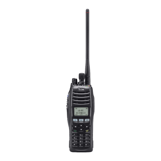
- Page 1 INSTRUCTION MANUAL VHF P25 TRUNKING HANDHELD TRANSCEIVERS iF9011 series UHF P25 TRUNKING HANDHELD TRANSCEIVERS iF9021 series iF9023 series The photo shows the 10-key type VHF transceiver.
-
Page 2: Explicit Definitions
Exchange Legal Controls. Please consult with your dealer or sales representative for details. Icom, Icom Inc. and the Icom logo are registered trademarks of Icom Incor- porated (Japan) in Japan, the United States, the United Kingdom, Germany, France, Spain, Russia, Australia, New Zealand, and/or other countries. -
Page 3: Fcc Information
#5,870,405, #5,826,222, #5,754,974, #5,701,390, #5,715,365, cian for help. #5,649,050, #5,630,011, #5,581,656, #5,517,511, #5,491,772, #5,247,579, #5,226,084 and #5,195,166. CAUTION: Changes or modifications to this transceiver, not expressly approved by Icom Inc., could void your authority to operate this transceiver under FCC regulations. -
Page 4: Precautions
Icom radios or Icom chargers. Only Icom battery areas with temperatures below –20°C (–4°F) or above +60°C (+140°F). packs are tested and approved for use with Icom radios or charged with Icom chargers. Using third-party or counterfeit DO NOT modify the radio. -
Page 5: Table Of Contents
TABLE OF CONTENTS IMPORTANT ................i 5 BATTERY CASE ............21 EXPLICIT DEFINITIONS ............i ■ Optional battery case (BP-237) ........21 FCC INFORMATION ............ii 6 SPEAKER MICROPHONE ..........22 ABOUT IPR ................ii ■ Optional speaker microphone (HM-184/HM-184H) ..22 VOICE CODING TECHNOLOGY ......... ii PRECAUTIONS .............. -
Page 6: Accessories
ACCESSORIES ■ Supplied accessories D Battery pack To attach the battery pack: The following accessories are supplied. Slide the battery pack on the back of the transceiver in the direc- tion of the arrow (q), then lock it with the battery release button. Flexible Battery pack •... -
Page 7: Accessories
ACCESSORIES D Belt clip D Connector cover To attach the belt clip: Attach the connector cover when the optional equipment is q Release the battery pack if it is attached. not used. w Slide the belt clip in the direction of the arrow until the belt To attach the connector cover: clip is locked and makes a ‘click’... -
Page 8: Panel Description
PANEL DESCRIPTION ■ Front panel e LED INDICATOR ➥ Lights green while receiving a signal, or when the squelch is open. ➥ Lights red while transmitting. ➥ The LED indicator indicates some information. (Non- display type only) (p. 16) r DEALER-PROGRAMMABLE ABC SWITCH Speaker Desired function can be programmed to each position Microphone... - Page 9 PANEL DESCRIPTION t CHANNEL INDICATOR !1 10-KEYPAD (10-key type only) ➥ Lights white according to the “Backlight” setting of the The keypad allows you to enter digits to: user set mode. • Select memory channels, tone channels and DTMF codes (while in the DTMF code channel selection mode.) ➥...
-
Page 10: Function Display (Simple/10-Key Types Only)
PANEL DESCRIPTION ■ Function display (Simple/10-key types only) t SCRAMBLER INDICATOR Appears when the voice scrambler or encryption function is activated. y BELL INDICATOR 001 ch-01 Appears/blinks when the matched signal is received, ac- cording to the pre-programming. IC-F9011 u TELEPHONE INDICATOR Appears when a phone call* is received. -
Page 11: Programmable Function Keys
*Simple/10-key types only Indicate the programmed function of the front panel keys ([I], [II] and [III]). Consult your Icom dealer or system operator for details con- cerning your transceiver’s programming. See the operating guide for details of Analog, MDC and P25 Trunking/Conventional system operations. - Page 12 PANEL DESCRIPTION D For All types (Common operation) HOME KEY “HOME” PRIO A AND PRIO B KEYS “PRA” “PRB” Push to return to the stand-by mode. Push to select Priority A or Priority B channel. • After editing some information that requires to be memorized, push this key to save the editing contents in the memory before returning MR-CH 1, MR-CH 2, MR-CH 3 AND MR-CH 4 KEYS to the stand-by mode.
- Page 13 PANEL DESCRIPTION D For All types (Different operation with Non-display type) SURVEILLANCE KEY “SURV” When the following key functions are programmed to Non- display type, the key functions may be limited and some key When this function is turned ON, the beep is not emitted and functions should be operated differently from Simple and the LCD backlight does not light when a signal is received or 10-key types.
- Page 14 PANEL DESCRIPTION PRIO A REWRITE AND PRIO B REWRITE KEYS D For Simple/10-key types only “PRAR” “PRBR” Following key functions cannot be programmed to Non-dis- ❍ For Simple/10-key types play types. ➥ Push to select Priority A or Priority B channel. ➥...
- Page 15 PANEL DESCRIPTION MENU AND MENU ➤ KEYS CLOCK KEY “CLCK” ] and [Menu ➤] can only be assigned to [Ω] and ( [Menu Push to indicate the current time on the LCD. (p. 15) [≈], respectively.) • While the current time is indicated, push and hold this key for The menu mode is available when either [Menu ] or 1 sec.
-
Page 16: Panel Description
PANEL DESCRIPTION D For ABC and Toggle switches only ZONE SWITCH SURVEILLANCE SWITCH Selects the pre-programmed zone directly. Turns the surveillance function ON or OFF. When this function is turned ON, the beep is not emitted and PRIO A AND PRIO B SWITCHES the LCD backlight does not light when a signal is received or Selects Priority A or Priority B channel. -
Page 17: Basic Operation
BASIC OPERATION ■ Turning power ON ■ Channel selection • Prior to using the transceiver for the first time, the battery Several types of channel selections are available. Methods pack must be fully charged for optimum life and opera- may differ according to your system set up. tion. -
Page 18: Receiving And Transmitting
BASIC OPERATION ■ Receiving and transmitting D Transmitting notes NOTE: Transmitting without an antenna may damage the • Transmit inhibit function transceiver. See p. 1 for accessory attachments. The transceiver has several inhibit functions which restrict Receiving: transmission under the following conditions: q Rotate [VOL] to turn the power ON. -
Page 19: User Set Mode
BASIC OPERATION ■ User set mode You can “customize” the transceiver operation to suit your preferences and operating style. Entering the user set mode: q Hold down [User Set Mode] for 1 second to enter the user set mode. w Push [User Set Mode] one or more times to select the ap- propriate item. -
Page 20: Clock Function
BASIC OPERATION ■ Clock function D Time and date settings The transceiver indicates the current time and date when [Clock] is pushed. And you can change the indication format q Push [Clock] to indicate the current time and date on the and time/date settings. -
Page 21: Led Indicator (Non-Display Type Only)
BASIC OPERATION ■ LED indicator (Non-display type only) The LED indicator indicates some information as follows; (Ref.; R=Red, G=Green, O=Orange) r Push [CH Up] or [CH Down] to set the selected item. • TX: Lights Red while transmitting a signal. 12HR 03:00PM •... -
Page 22: Battery Charging
• R WARNING! Immediately stop using the battery pack if it emits an abnormal odor, heats up, or is discolored or de- formed. If any of these conditions occur, contact your Icom dealer or distributor. - Page 23 0˚C to +40˚C (+32˚F to • BE SURE to replace the battery pack with a new one ap- +104˚F). Icom recommends charging the battery at +20˚C proximately five years after manufacturing, even if it still (+68˚F). The battery pack may heat up or rupture if charged holds a charge.
-
Page 24: Optional Battery Chargers
BATTERY CHARGING ■ Optional battery chargers D Rapid charging with the BC-119N+AD-110 The optional BC-119N rapidly charges the Li-Ion battery pack. D AD-110 installation Charging time: Approximately 4 hours for the BP-254. The following items are additionally required. The AD-110 must be installed into the BC- charger adapter •... -
Page 25: Battery Charging
BATTERY CHARGING D Rapid charging with the BC-121N+AD-110 IMPORTANT: Battery charging caution The optional BC-121N can simultaneously charge up to 6 Li- Ensure the guide tabs on the battery pack are correctly ion battery packs. aligned with the guide rails inside the charger adapter. Charging time: Approximately 4 hours for the BP-254. -
Page 26: Battery Case
BATTERY CASE ■ Optional battery case (BP-237) The optional battery case uses 6 × AA (LR6) size alkaline Fig.1 Latch BP-237 batteries. The battery case offers low output power. q Hook your finger under the latch, and open the cover in the direction of the arrow (q). -
Page 27: Speaker Microphone
SPEAKER MICROPHONE ■ Optional speaker microphone (HM-184/HM-184H) D Description D To attach Attach the connector of the speaker-microphone into the multi connector on the transceiver and tighten the screw with Microphone a coin or flat head screwdriver. Speaker Belt clip PTT SWITCH Push and hold to transmit;... -
Page 28: Options
OPTIONS D BATTERY PACKS D CABLES • CP-23L cigarette lighter cable Battery pack Voltage Capacity Battery life* Allows charging of the battery pack through a 12 V cigarette 2900 mAh (min.) lighter socket. (For BC-119N) BP-254* 7.4 V 9.5 hrs. 3040 mAh (typ.) •... -
Page 29: D Other Options
☞ Continues to the next page mance when used with an Icom transceiver. Icom is not responsible for the destruction or damage to an Icom transceiver in the event it is used with equipment that is not manu- factured or approved by Icom. - Page 30 OPTIONS D About VS-1MC (Continued) ptt case VOX gain and delay adjustment • VOX Delay q Attach the connector of the VS-1MC into the multi-connec- The VOX delay time can be set from 0.5 to 3.0 sec. (0.5 sec. tor on the transceiver and tighten the screw. step) for a convenient interval before returning to receive.
-
Page 31: Safety Training Information
A proper antenna is the antenna supplied with this radio be used only during the course of employment by in- by Icom Inc. or antenna specifically authorized by Icom Inc. for use dividuals aware of the hazards, and the ways to mini- with this radio. - Page 32 A-6662D-1US-i Printed in Japan © 2008−2015 Icom Inc. 1-1-32 Kamiminami, Hirano-ku, Osaka 547-0003, Japan Printed on recycled paper with soy ink.
Need help?
Do you have a question about the iC-F9011 series and is the answer not in the manual?
Questions and answers