Bunn JDF-4 Installation & Operating Manual
Hide thumbs
Also See for JDF-4:
- Installation and operating manual (32 pages) ,
- Use & care instructions (2 pages)
Table of Contents
Advertisement
Quick Links
BUNN
®
JDF-4
Prior to S/N 0005473
DISCONTINUED VERSION
The information in this manual
is no longer current.
INSTALLATION & OPERATING MANUAL
BUNN-O-MATIC CORPORATION
POST OFFICE BOX 3227
SPRINGFIELD, ILLINOIS 62708-3227
PHONE: (217) 529-6601 FAX: (217) 529-6644
www.bunnomatic.com
33854.0000 09/05 ©2001 Bunn-O-Matic Corporation
Advertisement
Table of Contents

Related Manuals for Bunn JDF-4


Summary of Contents for Bunn JDF-4
- Page 1 Prior to S/N 0005473 DISCONTINUED VERSION The information in this manual is no longer current. INSTALLATION & OPERATING MANUAL BUNN-O-MATIC CORPORATION POST OFFICE BOX 3227 SPRINGFIELD, ILLINOIS 62708-3227 PHONE: (217) 529-6601 FAX: (217) 529-6644 www.bunnomatic.com 33854.0000 09/05 ©2001 Bunn-O-Matic Corporation...
-
Page 2: Table Of Contents
SOLE OPTION AS SPECIFIED HEREIN, TO REPAIR, REPLACEMENT OR REFUND. In no event shall BUNN be liable for any other damage or loss, including, but not limited to, lost profits, lost sales, loss of use of equipment, claims of Buyer’s customers, cost of capital, cost of down time, cost of substitute equipment, facilities or services, or any other special, incidental or consequential damages. -
Page 3: User Notices
(When Hot Water source is not available) NOTES: • Use Bunn-O-Matic tubing, part number 32759.10XX for all connections. (See Illustrated Parts Catalog for complete part number) • Clamp all hose connections with Bunn-O-Matic part number 21275.0003 (hose clamp) 34054.0000A 10/01 ©2001 BUNN-O-MATIC CORPORATION 34054.0000 33854 092101... -
Page 4: Initial Set-Up & Electrical Requirements
JDF-4 is designed for indoor use only. Set the dispenser on the counter where it will be used. The JDF-4 requires a minimum of 4 inches (102 mm) of air clearance at the rear and 8 inches (203 mm) of air clearance above the dispenser. Minimal clearance is required between the dispenser sides and the wall or another appliance. -
Page 5: Plumbing Requirements
BUNN-O-MATIC (part number 32759.10_ _ [see Illustrated Parts Catalog for complete part number.]) BUNN-O-MATIC does not recommend the use of saddle valves to install the dispenser. The size and shape of the hole(s) made in the supply line(s) by saddle valves may restrict water flow. -
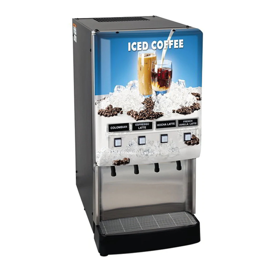
Page 6: Operating Controls
OPERATING CONTROLS Refrigeration Switch The refrigeration switch is located on the top of the dispenser near the left rear corner. This switch controls power to the compressor and the condenser fan motor. P2262.60 FIG 2 Refrigeration Switch Sanitize Switch The sanitize switch is located behind the drip tray in the lower left corner of the chassis. - Page 7 OPERATING CONTROLS (cont.) FIG 4 Press and Hold Models A. Product Dispense Switch Pressing and holding switch will initiate product flow from the respective nozzle; releasing the switch will stop the flow. B. Chilled Water Dispense Switch Pressing and holding switch will initiate chilled water flow from the nozzle; releasing the switch will stop the flow.
-
Page 8: Initial Fill
INITIAL FILL CAUTION: The dispenser must be disconnected from the power source throughout the initial fill except when specified in the instructions. 1. Remove drip tray assembly and splash panel from the dispenser. 2. Pull the overflow tube from its retaining clip and place the end into an empty 64 fluid ounce (2 liter) container. 3. - Page 9 INITIAL FILL (cont) Ambient Concentrates (Optional) 1. Install an Ambient Concentrate Conversion Kit (BUNN-O-MATIC part number 33699.0000) per the instructions provided in the kit. 2. Attach the concentrate product hose to the appropriate concentrate line located behind the dispenser’s splash panel.
-
Page 10: Dispenser Use
DISPENSER USE Press and Hold Models (Refer to Fig 4) 1. Place a cup on the drip tray beneath the desired dispensing nozzle. 2. Press and hold the “Product Dispense” or “Chilled Water” switch until the beverage/water reaches the desired level, then release. - Page 11 FIG 6 Dispense/Rinse Switch 4. Place the empty container under the dispense nozzle to catch the rinse water. (CAUTION: THE BUNN JUICE DISPENSER CAN BE PLUMBED FOR A HOT WATER RINSE. RINSE WATER CAUGHT IN THIS STEP SHOULD BE HANDLED WITH EXTREME CARE.) 5.
-
Page 12: Cleaning
CLEANING (cont) 6. Select the dispense stations by pressing the “Dispense Switch” for that station. Use the “+/Stop Switch” for portion contol dispensers. The “REFILL” indicator will light and the beeper will sound for the dispense head selected. 7. Once the dispense heads have been selected, press and hold the “Sanitize Switch” for 5 seconds again to initiate the automatic cycle. - Page 13 21. Insert the plastic elbows into the new pump tubing and secure it with the clamps. 22. Apply lubricant (BUNN-O-MATIC part number M2548.0000) to the new pump tubing’s rotor side. 23. Gently wrap the new pump tubing around the pump’s rotor, making sure that the elbows and clamps end up on the top-side of the pump body and don’t protrude through the exit slots.
-
Page 14: Adjustments & Optional Settings
Press and hold the “+/Stop Switch” Fig 5, until water and concentrate begin flowing freely from the Flow Separator Assembly nozzles. 6. Place the empty brixing cup (BUNN-O-MATIC part number 33095.0000) under the Flow Separator Assembly nozzles, small (concentrate) chamber to the left and large (water) chamber to the right. - Page 15 “PROGRAM” indicator begins flashing. 2. Place a graduated measuring cup or the large chamber of the empty brixing cup (BUNN-O-MATIC part number 33095.0000) under the appropriate dispense nozzle. 3. Press and hold the desired “Product Dispense Switch” Fig 4 (“+/Stop P2253.70...
- Page 16 1. Enter the “Pump Speed Programming” mode by simultaneously pressing both “Hidden Switches”. Note that the beeper sounds twice and that the “PROGRAM” indicator begins flashing. 2. Place a graduated measuring cup or the large chamber of the empty brixing cup (BUNN-O-MATIC part number 33095.0000) under the appropriate dispense nozzle.
- Page 17 ADJUSTMENT & OPTIONAL SETTINGS (cont) b) In a 5 second period, press and release the “Chilled Water Switch” the number of times that you want the password set to (maximum of 10.) For example: If you want the password set to 3, press and release the “Chilled Water Switch”...
- Page 18 ADJUSTMENT & OPTIONAL SETTINGS (cont) Password Protection The programming modes and service lockout function may be password protected to prevent accidental or unauthorized access to these features. The dispenser is shipped from the factory with a password of “0” (no password.) 1.
- Page 19 Dispense Fault List “REFILL” indicator Beeper Fault 2 flashes 2 beeps Dispense station locked out. 3 flashes 3 beeps DISPENSE/RINSE sensing fault. 4 flashes 4 beeps DISPENSE/RINSE knob mis-positioned. 5 flashes 5 beeps Pump motor stalled/speed sensor inoperative. All “REFILL” 3 beeps Dispenser locked out.
-
Page 20: Function Lists
Dip Switch Function List Dip Switch Controls “REFILL” indicator when “concentrate out” is detected. Inactive Active Lockout dispense components when “concentrate out” is detected. Inactive Active (Note) Number of positions that can dispense/rinse simultaneously. Rinse timer Audio feedback during dispenses. Future use. -
Page 21: Coolant Diagram
COOLANT SCHEMATIC DIAGRAM 33854 092101... -
Page 22: Schematic Wiring Diagram
(Portion Control Models) SHEILD #1 DISPENSE #2 DISPENSE #3 DISPENSE #4 DISPENSE WHI/VIO RED/BLK WHI/ORN RED/BLK WHI/BLU RED/BLK WHI/YEL RED/BLK ICE WATER DISPENSE RED/BLK 120 VOLTS A C 2 WIRE SINGLE PHASE 33457.0000F 08/03 © 2000 BUNN-O-MATIC CORPORATION 33854 082803...
Need help?
Do you have a question about the JDF-4 and is the answer not in the manual?
Questions and answers