Table of Contents
Advertisement
Quick Links
Advertisement
Table of Contents

Related Manuals for HAMPTON BAY YG419-WH


Summary of Contents for HAMPTON BAY YG419-WH
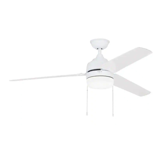
- Page 1 Item #593-559 Model #YG419-WH USE AND CARE GUIDE CARRINGTON 60 INCH CEILING FAN Questions, problems, missing parts? Before returning to the store, call Hampton Bay Customer Service 8 a.m. - 6 p.m., EST, Monday-Friday 1-877-527-0313 HAMPTONBAY.COM THANK YOU THANK YOU...
-
Page 2: Table Of Contents
Table of Contents Table of Contents ............Operation ..............Pull Chain Operating Instructions .......... Safety Information ............Reverse Switch Operating Instructions ........Warranty ................. Care and Cleaning ............Pre-installation .............. Troubleshooting ............Specifications ................Tools Required ................. Service Parts ............... Hardware Included .............. -
Page 3: Safety Information
Safety Information To reduce the risk of electric shock, ensure electricity has WARNING: To reduce the risk of electrical shock or fire, do been turned off at the circuit breaker or fuse box before not use this fan with any solid-state fan speed control device. beginning. -
Page 4: Warranty
Warranty We warrant the fan motor to be free from defects in workmanship and material present at time of shipment from the factory for a period of lifetime after the date of purchase by the original purchaser. We also warrant that all other fan parts, excluding any glass or acrylic blades, to be free from defects in workmanship and material at the time of shipment from the factory for a period of one year after the date of purchase by the original purchaser. -
Page 5: Hardware Included
Pre-Installation (continued) HARDWARE INCLUDED HARDWARE INCLUDED NOTE: Hardware shown to actual size unless noted otherwise in the table below. Part Part Description Description Quantity Quantity Plastic wire nut Blade attachment screw and rubber washer Mounting bracket screw (preassembled) Balance kit (not to scale) Clevis pin (preassembled) Cotter pin (preassembled) Collar setscrew (preassembled) -
Page 6: Package Contents
Pre-Installation (continued) PACKAGE CONTENTS PACKAGE CONTENTS Part Part Description Description Quantity Quantity Part Part Description Description Quantity Quantity Mounting bracket (preassembled) Blade arm Canopy Blade Canopy bottom cover Medallion Hanger ball/downrod assembly Switch housing Coupling cover Light kit Fan motor assembly Glass shade... -
Page 7: Installation
Installation MOUNTING OPTIONS MOUNTING OPTIONS NOTE: WARNING: To reduce the risk of fire, electric shock, or You may need a longer downrod to maintain proper blade clearance when installing on a steep, sloped ceiling. personal injury, mount the fan to an outlet box marked The maximum angle allowable is 18°... -
Page 8: Assembly
Assembly Preparing the canopy Preparing the motor □ □ Remove the canopy bottom cover (C) from the canopy Remove the clevis pin (EE) and cotter pin (FF), and (B) by turning the canopy bottom cover (C) counter- loosen the two collar setscrews (GG) from the fan clockwise. -
Page 9: Hanging The Fan
Assembly — Hanging the Fan Hanging the fan from the mounting Attaching the mounting bracket bracket to the electrical box WARNING: To reduce the risk of fire, electric shock or WARNING: The tab in the ring must rest in the groove of other personal injury, mount the fan only to an outlet box or the hanger ball/downrod assembly (D). - Page 10 Assembly — Hanging the Fan (continued) Making the electrical connections WARNING: To avoid possible electrical shock, be sure electricity is turned off at the main fuse box before wiring. WARNING: Check to see that all connections are tight, including ground, and that no bare wire is visible at the wire nuts (AA), except for the ground wire.
-
Page 11: Attaching The Canopy
Assembly — Hanging the Fan (continued) Attaching the canopy Installing the canopy bottom cover □ Attach the canopy bottom cover (C) to the mounting WARNING: Make sure the tab on the mounting bracket (A) bracket screw (CC) heads on the bottom of the properly sits in the groove in the hanger ball (D) before canopy (B) by inserting the screw heads into the key attaching the canopy (B) to the mounting bracket (A) by... -
Page 12: Attaching The Fan Blades
Assembly — Attaching the Fan Blades Removing the rubber Attaching the blades to the packing mounts blade arms □ □ The fan motor assembly (F) is shipped with rubber Attach the blades (H) to the blade arms (G) using the three blade attachment screws and rubber washers packing mounts (VV) to prevent movement during (BB) and the medallions (I). -
Page 13: Installing The Light Kit
Assembly — Installing the Light Kit Attaching the switch housing Attaching the light kit to to the mounting ring the switch housing □ Remove one of the three light kit mounting screws CAUTION: Before starting installation, disconnect the (JJ) from the switch housing (J) and loosen the other power by turning off the circuit breaker or removing the fuse two screws (JJ). - Page 14 Assembly — Installing the Light Kit (continued) Installing the light bulbs Installing the glass shade □ Raise the glass shade (L) up against the light kit (K) CAUTION: Before starting installation, disconnect the and secure the glass shade (L) to the fan by turning power by turning off the circuit breaker or removing the fuse the glass shade (L) counterclockwise until snug.
-
Page 15: Operation
Operation PULL CHAIN OPERATING INSTRUCTIONS PULL CHAIN OPERATING INSTRUCTIONS Attach the two pull chains and fobs (KK) to the pull chains located on the switch housing (J). Turn on the power and check the operation of the fan. The pull chain controls the fan speed as follows: 1 pull - High, 2 pulls - Medium, 3 pulls - Low, and 4 pulls - Off. -
Page 16: Care And Cleaning
Care and Cleaning Do not □ Check the support connections, brackets, and blade □ Use water when cleaning. Water could damage the motor, attachments twice a year. Make sure they are secure. or the wood, or possibly cause an electrical shock. Because of the fan’s natural movement, some connections may become loose over time. -
Page 17: Troubleshooting
Troubleshooting (continued) Problem Solution □ Check that all blade and blade arm screws are secure. □ Most fan wobble problems are caused when blade levels are unequal. Check this level by selecting a point on the ceiling above the tip of one of the blades. Measure from a point on the center of each blade The fan wobbles. -
Page 18: Service Parts
Service Parts Part Part Description Description Part Part Description Description Mounting bracket (preassembled) Plastic wire nut Canopy Blade attachment screw and rubber washer Canopy bottom cover Mounting bracket screw (preassembled) Hanger ball/downrod assembly Balance kit Coupling cover Clevis pin (preassembled) Fan motor assembly Cotter pin (preassembled) 3 Blade arms... - Page 19 Questions, problems, missing parts? Before returning to the store, call Hampton Bay Customer Service 8 a.m. - 6 p.m., EST, Monday-Friday 1-877-527-0313 HAMPTONBAY.COM Retain this manual for future use. YG419000001-Y...
Need help?
Do you have a question about the YG419-WH and is the answer not in the manual?
Questions and answers