Table of Contents
Advertisement
Advertisement
Table of Contents

Subscribe to Our Youtube Channel
Related Manuals for HAMPTON BAY ETRIS 52


Summary of Contents for HAMPTON BAY ETRIS 52
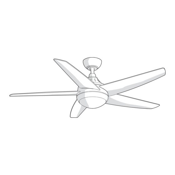
- Page 1 Item #593-558 Model #YG327B-BN USE AND CARE GUIDE ETRIS 52 INCH CEILING FAN Questions, problems, missing parts? Before returning to the store, call Hampton Bay Customer Service 8 a.m. - 6 p.m., EST, Monday-Friday 1-855-HD-HAMPTON HAMPTONBAY.COM THANK YOU THANK YOU...
-
Page 2: Table Of Contents
Table of Contents Table of Contents ............Operation ..............Remote Control Operating Instructions ........Safety Information ............Installing the Remote Control Holder ........Reverse Switch Operating Instructions ........Warranty ................. Care and Cleaning ............Pre-installation .............. Specifications ................Troubleshooting ............Tools Required ................. -
Page 3: Safety Information
Safety Information To reduce the risk of electric shock, ensure electricity has WARNING: To reduce the risk of electrical shock or fire, do been turned off at the circuit breaker or fuse box before not use this fan with any solid-state fan speed control device. beginning. -
Page 4: Warranty
Warranty We warrant the fan motor to be free from defects in workmanship and material present at time of shipment from the factory for a period of lifetime after the date of purchase by the original purchaser. We also warrant that all other fan parts, excluding any glass or acrylic blades, to be free from defects in workmanship and material at the time of shipment from the factory for a period of one year after the date of purchase by the original purchaser. -
Page 5: Hardware Included
Pre-Installation (continued) HARDWARE INCLUDED HARDWARE INCLUDED NOTE: Hardware shown to actual size unless noted otherwise in the table below. Part Part Description Description Quantity Quantity Plastic wire nut Mounting bracket screw (preassembled) Blade attachment screw and lock washer Balance kit (not to scale) Receiver (not to scale) Remote control (not to scale) 12V MN21/A23 battery (not to scale) -
Page 6: Package Contents
Pre-Installation (continued) PACKAGE CONTENTS PACKAGE CONTENTS Part Part Description Description Quantity Quantity Part Part Description Description Quantity Quantity Mounting bracket (preassembled) Blade Canopy Blade support plate Canopy bottom cover Light kit mounting plate Hanger ball/downrod assembly LED Light kit Coupling cover Glass shade Fan motor assembly... -
Page 7: Installation
Installation MOUNTING OPTIONS MOUNTING OPTIONS NOTE: WARNING: You may need a longer downrod to maintain proper To reduce the risk of fire, electric shock, or blade clearance when installing on a steep, sloped ceiling. personal injury, mount the fan to an outlet box marked The maximum angle allowable is 18°... -
Page 8: Assembly
Assembly Preparing the canopy Preparing the motor □ □ Remove the canopy bottom cover (C) from the canopy Remove the clevis pin (KK) and cotter pin (LL), and (B) by turning the canopy bottom cover (C) counter- loosen the two collar setscrews (MM) from the fan clockwise. -
Page 9: Hanging The Fan
Assembly — Hanging the Fan Hanging the fan from the mounting Attaching the mounting bracket bracket to the electrical box WARNING: To reduce the risk of fire, electric shock or WARNING: The tab in the ring must rest in the groove of other personal injury, mount the fan only to an outlet box or the hanger ball/downrod assembly (D). - Page 10 Assembly — Hanging the Fan (continued) Preparing the receiver and remote control WARNING: To avoid possible electrical shock, be sure electricity is turned off at the main fuse box before wiring. CAUTION: Do not use with a wall light dimmer switch. If you feel you do not have enough electrical wiring knowledge or experience, have your fan installed by a licensed electrician.
- Page 11 Assembly — Hanging the Fan (continued) Making the electrical connections □ If your outlet box (PP) has a ground wire (HHH) (green NOTE: The fan must be installed at a maximum distance of or bare copper) connect it to the fan ground wires (III); 20 feet from the remote control for proper signal transmission otherwise connect the hanger ball/downrod assembly between the remote control and the fan's receiving unit.
- Page 12 Assembly — Hanging the Fan (continued) Attaching the canopy Installing the canopy bottom cover □ Attach the canopy bottom cover (C) to the mounting WARNING: Make sure the tab on the mounting bracket (A) bracket screw (BB) heads on the bottom of the properly sits in the groove in the hanger ball/downrod canopy (B) by inserting the screw heads into the key assembly (D) before attaching the canopy (B) to the mounting...
-
Page 13: Attaching The Fan Blades
Assembly — Attaching the Fan Blades Attaching the Fan Blades WARNING: To reduce the risk of personal injury, do not bend the blades (G) while installing, balancing the blades (G), or cleaning the fan. WARNING: Remove the four rubber packing mounts (UU) from the fan motor assembly and discard prior to attaching the blades (G). -
Page 14: Installing The Led Light Kit
Assembly — Installing the Light Kit Attaching the light kit mounting Attaching the LED light kit to plate to the mounting ring the light kit mounting plate □ Remove one of the three light kit mounting plate CAUTION: Before starting installation, disconnect the screws (NN) from the mounting ring (JJJ) and loosen power by turning off the circuit breaker or removing the fuse the other two screws. - Page 15 Assembly — Installing the Light Kit (continued) Installing the glass shade □ Raise the glass shade (K) up against the light kit (J) and secure the glass shade (K) to the fan by turning the glass shade (K) clockwise until snug. DO NOT OVERTIGHTEN.
-
Page 16: Operation
Operation REMOTE CONTROL OPERATING INSTRUCTIONS REMOTE CONTROL OPERATING INSTRUCTIONS □ Install the 12V MN21/A23 battery (GG) (included) into the remote control (FF). To prevent damage to the remote control (FF), remove the battery if not used for long periods. □ Restore power to the ceiling fan and test for proper operation. HI, MED, LOW buttons: set the fan speed. -
Page 17: Reverse Switch Operating Instructions
Operation (continued) REVERSE SWITCH OPERATING INSTRUCTIONS The reverse switch is located on the top of the motor housing. Slide the switch to the left for warm weather operation. Slide the switch to the right for cool weather operation. NOTE: Wait for the fan to stop before reversing the direction of the blade rotation. -
Page 18: Troubleshooting
Troubleshooting WARNING: Make sure the power is off at the electrical panel box before you attempt any repairs. Refer to step 7 “Making the Electrical Connections” on page 11. Problem Solution □ Check the main and branch circuit fuses or breakers. □... -
Page 19: Service Parts
Service Parts Part Part Description Description Part Part Description Description Mounting bracket (preassembled) Blade attachment screw and lock washer Canopy Balance kit Canopy bottom cover Receiver Hanger ball/downrod assembly Remote control Coupling cover 12V MN21/A23 battery Fan motor assembly Remote control holder 5 Blades Remote control holder mounting screw 5 Blade support plates... - Page 20 Questions, problems, missing parts? Before returning to the store, call Hampton Bay Customer Service 8 a.m. - 6 p.m., EST, Monday-Friday 1-855-HD-HAMPTON HAMPTONBAY.COM Retain this manual for future use. YG327B000001-Y...
Need help?
Do you have a question about the ETRIS 52 and is the answer not in the manual?
Questions and answers