Table of Contents
Advertisement
Quick Links
Advertisement
Table of Contents

Related Manuals for Dynacord Promatrix 6000 PMX-2P500


Summary of Contents for Dynacord Promatrix 6000 PMX-2P500
- Page 1 Promatrix 6000 Amplifier PMX-2P500 en | Operation manual...
-
Page 3: Table Of Contents
Promatrix 6000 Amplifier Table of contents | en Table of contents Safety Short information System overview Front panel Rear panel Parts included Installation Connection Audio inputs Audio output Supply voltage CAN BUS Configuration Setting the CAN address Displaying the CAN baud rate Configuring the CAN baud rate Operation Stand-alone mode... -
Page 4: Safety
en | Safety Promatrix 6000 Amplifier Safety Danger! High risk: This symbol indicates an imminently hazardous situation such as "Dangerous Voltage" inside the product. If not avoided, this will result in an electrical shock, serious bodily injury, or death. Warning! Medium risk: Indicates a potentially hazardous situation. - Page 5 Promatrix 6000 Amplifier Safety | en 13. Use only with the cart, stand, tripod, bracket or table specified by the manufacturer, or sold with the apparatus. – When a cart is used, use caution when moving the cart/ apparatus combination to avoid injury from tip-over. Quick stops, excessive force, and uneven surfaces may cause the appliance and cart combination to overturn.
- Page 6 en | Safety Promatrix 6000 Amplifier Danger! Object and Liquid entry – Never push objects of any kind into this apparatus through openings as they may touch dangerous voltage points or short-out parts that could result in a fire or electric shock. Never spill liquid of any kind on the apparatus. 25.
- Page 7 Promatrix 6000 Amplifier Safety | en Warning! To avoid electric shock, do not connect safety extra-low voltage (SELV) circuits to telephone- network voltage (TNV) circuits. LAN ports contain SELV circuits, and WAN ports contain TNV circuits. Some LAN and WAN ports both use RJ‑45 connectors. Use caution when connecting cables.
-
Page 8: Short Information
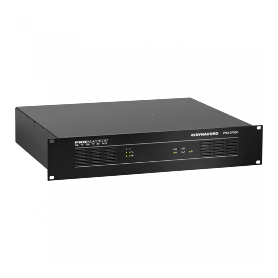
en | Short information Promatrix 6000 Amplifier Short information The PMX-2P500 class-D amplifier is a 2 ✕ 500 W professional audio amplifier for evacuation purposes. It can be operated from both the mains and a DC supply. The output voltage is galvanically insulated and is constantly monitored for ground fault. -
Page 9: System Overview
Promatrix 6000 Amplifier System overview | en System overview Front panel Number Symbol Element Description Signal clip Indicates the signal level of the amplifier channel: indicator light • Green = The output signal is 18 dB below clip level • Yellow = The output signal is clipping or the integrated limiter of the amplifier is limiting the output signal. - Page 10 en | System overview Promatrix 6000 Amplifier Number Symbol Element Description Recessed button The button is protected to prevent it from being pressed accidentally. Use a pointed object (such as a ballpoint pen) to press the button. This button has the following functions if the CAN address of the device is not set to 00: •...
- Page 11 Promatrix 6000 Amplifier System overview | en Number Symbol Element Description Standby indicator This indicator lights up green when the device is in light standby mode. Power indicator This indicator lights up green when the power light supply is OK. Operation manual 18-Jun-2015 | 04 | F01U306848...
-
Page 12: Rear Panel
en | System overview Promatrix 6000 Amplifier Rear panel Number Element Description AC power input and power switch Grounding screw Ground connection for DC only systems. DC power input CAN BUS port Connection with CAN bus, e.g. controller. CAN ADDRESS selector switch HIGH-byte and LOW-byte for configuring the CAN address of the device. -
Page 13: Parts Included
Euroblock connector 3-pole (Phoenix, MC 1,5/3-STF-3,81, Nr. 1827716, F. 01U.104.680) for audio input Euroblock connector 6-pole (Phoenix, MC 1,5/6-ST-3,81, 1827745, F.01U. 104.179) for audio outputs Foot stand (self-adhesive) Operation manual Important safety instructions Warranty For information regarding the warranty, see www.dynacord.com Operation manual 18-Jun-2015 | 04 | F01U306848... -
Page 14: Installation
en | Installation Promatrix 6000 Amplifier Installation This device has been designed to be installed horizontally in a conventional 19” rack cabinet. In general, an installation location must be selected in which the device is protected from the following conditions: •... - Page 15 Promatrix 6000 Amplifier Installation | en Figure 5.2: Stacking of devices using the supplied foot stands (example with 3 devices, rack mount rails are used for the bottom device only) Heat development The table in chapter Specification can be used to determine the requirements for power supply and supply lines.
-
Page 16: Connection
en | Connection Promatrix 6000 Amplifier Connection Audio inputs The power amplifier has four audio input channels. With the help of integrated pilot tone monitoring, a missing or faulty input signal can be detected reliably. Please refer to section Circuit diagram, page 32 for details about the internal audio routing of the device. RJ-45 The pin assignment of the LINE 1-4 IN / THRU audio input sockets allows connecting the power amplifier to the RJ-45 audio output socket of a controller using standard RJ-45 patch... - Page 17 Promatrix 6000 Amplifier Connection | en Euroblock The L1 or L2 audio inputs allow to connect local audio sources, e.g. in stand-alone mode. The audio signal L1 is mixed with input signal LINE IN 4 (provided via RJ-45) and amplified by amplifier output channel 1.
-
Page 18: Audio Output
en | Connection Promatrix 6000 Amplifier Figure 6.3: Unbalanced cabling Audio output The audio outputs on the device are galvanically insulated and are constantly monitored for ground fault. For each output channel there are 6 pins, two pins for 0V, two pins for 70V and two pins for 100V speaker lines. -
Page 19: Supply Voltage
Promatrix 6000 Amplifier Connection | en Supply voltage The device is normally operated via the AC mains input (120–240 V). In addition, a battery input is available for emergency power operation (24 V DC). Notice! If the AC and DC power inputs are used, it is recommended to connect AC power first, then switch on the device, then connect the DC power source. -
Page 20: Can Bus
en | Connection Promatrix 6000 Amplifier The device automatically switches to DC input in the event of failure of the mains supply voltage. For this input, connect a 24-volt DC source to the DC INPUT input. The scope of delivery for the device includes a 2-pin connector. Conductor cross-sections of 2 mm² to 6 mm²... - Page 21 Promatrix 6000 Amplifier Connection | en Figure 6.4: Assignment of the CAN port Figure 6.5: Assignment of the CAN connector Designation Cable color T568A T568B CAN_GND Green Orange CAN_H (+) Blue CAN_L (-) Blue stripes Table 6.2: Assignment of the CAN BUS interface Cable specification In accordance with the ISO 11898-2 standard, shielded twisted-pair cables with an impedance of 120 ohms must be used as the data transfer cable for the CAN bus.
- Page 22 en | Connection Promatrix 6000 Amplifier The following table allows initial estimates for the required cable cross-section for different bus lengths and various numbers of bus participants. Bus length (in m) Number of devices on the CAN Bus 0.25 mm² or AWG24 0.34 mm²...
-
Page 23: Configuration
Promatrix 6000 Amplifier Configuration | en Configuration Setting the CAN address The CAN address of the device is set using the two address selector switches HIGH and LOW. Addresses 1 to 250 (01 hex to FA hex) can be used in a CAN network. The address is set using the hexadecimal numbering system. -
Page 24: Displaying The Can Baud Rate
en | Configuration Promatrix 6000 Amplifier HIGH Address 0 to A 240 to 250 B to F Reserved Table 7.1: CAN addresses Displaying the CAN baud rate To display the CAN baud rate, press the Recessed button and keep the button pressed down for at least one second. -
Page 25: Operation
Promatrix 6000 Amplifier Operation | en Operation Fault monitoring The following functions of the power amplifier can be monitored: • Mains under-voltage • Battery under-voltage • Excessive temperature • Overload • Output voltage • Output current • Ground fault (in stand-alone mode only) •... - Page 26 en | Operation Promatrix 6000 Amplifier capacity is less than 5 μF, the Ground fault indicator light must not light up. After the resistor has been removed, the display and the malfunction message must continue to be shown. To reset the ground fault monitoring function, press the Recessed button. 18-Jun-2015 | 04 | F01U306848 Operation manual...
-
Page 27: Maintenance
Promatrix 6000 Amplifier Maintenance | en Maintenance Firmware update IRIS-Net can be used to update the firmware on the device. Depending on the CAN data rate used, the update will take one or more minutes to complete. Since development work is always being performed in relation to all system software, it may be necessary to update the firmware on the controller. -
Page 28: Technical Data
en | Technical data Promatrix 6000 Amplifier Technical data Specification Rated load impedance (output power) • 100 V 20 Ω (500 W) • 70 V 10 Ω (500 W) 2 ✕ 500 W Rated output power, 1 kHz, THD ≤ 1% Rated input voltage +6 dBu Max. - Page 29 Promatrix 6000 Amplifier Technical data | en Protection Audio input level limiter, RMS output power limiter, high temperature, DC, short circuit, mains undervoltage protection, DC supply undervoltage protection, inrush current limiter, ground fault Cooling Front-to-rear, temperature-controlled fans Operating temperature -5 °C to +45 °C Safety class Class I Electromagnetic environment...
-
Page 30: Standards
en | Technical data Promatrix 6000 Amplifier 10.1 Standards • EN 50130-4 • EN 50581 • EN 55103-1/2 • EN 61000-3-2/3 • EN 61000-6-3 • IEC 60065 • EN 60945 10.2 Power consumption 230 V/50 Hz operation BTU/h supply supply supply Standby 0.14 A... -
Page 31: Dimensions
Promatrix 6000 Amplifier Technical data | en 10.3 Dimensions Operation manual 18-Jun-2015 | 04 | F01U306848... -
Page 32: Circuit Diagram
en | Technical data Promatrix 6000 Amplifier 10.4 Circuit diagram Output Relay 100V IN1+ IN1- IN2+ 2.RJ45 IN2- analog audio IN3+ 4 IN 1 250W / 500W input Clipper / Limiter IN3- 250W Router Output IN4+ Transformer IN4- OUT1+ 100V OUT1- 4 IN 1 OUT2+... - Page 34 Bosch Security Systems B.V. Torenallee 49 5617 BA Eindhoven The Netherlands www.boschsecurity.com © Bosch Security Systems B.V., 2015...
Need help?
Do you have a question about the Promatrix 6000 PMX-2P500 and is the answer not in the manual?
Questions and answers