Sign In
Upload
Download
Table of Contents
Contents
Add to my manuals
Delete from my manuals
Share
URL of this page:
HTML Link:
Bookmark this page
Add
Manual will be automatically added to "My Manuals"
Print this page
×
Bookmark added
×
Added to my manuals
Manuals
Brands
Dynacord Manuals
Amplifier
X1201
Owner's manual
Dynacord X1201 Owner's Manual
Modular power amplifier
Hide thumbs
1
2
3
4
5
6
7
8
9
10
11
12
13
14
15
16
17
Table Of Contents
18
page
of
18
Go
/
18
Contents
Table of Contents
Bookmarks
Table of Contents
Important Safety Instructions
Important Service Instructions
Contents
X-Amps
Open Input and Output Architecture
Module Slots on the Front Panel
X-Amp Basic Version - Without Front Modules
The Modules
Example - DYNACORD V-Systems Modules
Power Amplifier Design and Protections
Back-EMF Protection
Peak Current Limiter
DC/HF Protection
Mounting
Cooling
Mains Power
Cabling
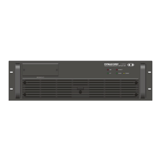
Front View
Module Slots
Limit
Out
POWER Switch
Power on Indicator
Front View
Input Modules
XI-11 Input Module
Output Modules
Xo-1 Output Module
GROUND-LIFT Switch
Grounding Screw
Specifications
Technical Specifications: X1201
Technical Specifications: X1202
Block Diagram
Dimensions (in MM)
Garantie
Warranty
Advertisement
Quick Links
1
Important Safety Instructions
2
Specifications
3
Technical Specifications: X1201
4
Technical Specifications: X1202
Download this manual
O W N E R ' S M A N U A L
X1201 / X 1202
M O D U L A R P O W E R A M P L IFIER
Table of
Contents
Previous
Page
Next
Page
1
2
3
4
5
Advertisement
Table of Contents
Need help?
Do you have a question about the X1201 and is the answer not in the manual?
Ask a question
Questions and answers
Related Manuals for Dynacord X1201
Amplifier Dynacord PM2600 Brochure & Specs
Dynacord system power amplifier owner's manual (2 pages)
Amplifier Dynacord XA 2600 Information Sheet For Builders And Architects
System processor power amplifier (4 pages)
Amplifier DYNACORD XA-3600 Owner's Manual
System amplifier (8 pages)
Amplifier Dynacord System Power Amp Xa 4000 Owner's Manual
Dynacord system power amp owner's manual (48 pages)
Amplifier Dynacord X 1202 Owner's Manual
Modular power amplifier (18 pages)
Amplifier Dynacord Professional Power Amplifiers Brochure & Specs
Professional power amplifiers (72 pages)
Amplifier Dynacord Xa 4000 Owner's Manual
System power amp (18 pages)
Amplifier Dynacord D 12-3A Specifications
Dynacord powered 3-way biamped cabinet 350 w + 150 w rms amplifier output power specification sheet (6 pages)
Amplifier Dynacord DSA 8405 Owner's Manual
Dynacord digital system amplifier owner's manual (40 pages)
Amplifier DYNACORD S 1200 Owner's Manual
Power amplifier (10 pages)
Amplifier Dynacord L300 Owner's Manual
Linear precision power amplifiers (20 pages)
Amplifier Dynacord PCL 1245 Owner's Manual
Pcl-series power amplifiers (40 pages)
Amplifier Dynacord L1300FD-AU Installation Manual
L series and c series fir-drive power amplifiers (45 pages)
Amplifier Dynacord PCA 2450 Specification Sheet
Two-channel processor-controlled power amplifier (4 pages)
Amplifier DYNACORD LX 1600 Owner's Manual
Switchmode precision (36 pages)
Amplifier Dynacord MV 503 Owner's Manual
Mixer amplifier (28 pages)
This manual is also suitable for:
X 1202
X1201
Table of Contents
Save PDF
Print
Rename the bookmark
Delete bookmark?
Delete from my manuals?
Login
Sign In
OR
Sign in with Facebook
Sign in with Google
Upload manual
Upload from disk
Upload from URL


Need help?
Do you have a question about the X1201 and is the answer not in the manual?
Questions and answers