Table of Contents
Advertisement
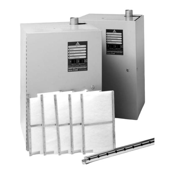
Series HC- 4100/4145/4300/4500
Installation, Operation and
Maintenance Instructions
Installation
Start-Up Procedure and Operation
Maintenance
Troubleshooting
PC Board Switch Data
Typical Wiring Schematic
Repair Parts
Humidistat Data
HumidiClean
Humidifiers
Table of Contents
™
Page
2 - 9
10 - 11
11 - 16
16 - 21
22
23 - 24
25 - 31
32 - 35
Bulletin 537-G
Advertisement
Table of Contents

Subscribe to Our Youtube Channel
Related Manuals for Armstrong HumidiClean HC-4100 Series


Summary of Contents for Armstrong HumidiClean HC-4100 Series
- Page 1 Bulletin 537-G ™ HumidiClean Series HC- 4100/4145/4300/4500 Humidifiers Installation, Operation and Maintenance Instructions Table of Contents Page Installation 2 - 9 Start-Up Procedure and Operation 10 - 11 Maintenance 11 - 16 Troubleshooting 16 - 21 PC Board Switch Data Typical Wiring Schematic 23 - 24 Repair Parts 25 - 31 Humidistat Data 32 - 35...
-
Page 2: Installation
Installation Please read and save these instructions. The Armstrong HumidiClean humidifier converts ordinary tap water or purified water to steam for distribution to raise the relative humidity level. To allow HumidiClean to function to its full capability, be certain to install in accordance with Armstrong recommendations. - Page 3 3. Site Selection. The humidifier should be installed in an easily accessible location. Do not install the unit where malfunction of the humidifier might cause damage to non-repairable, unreplaceable or priceless property. Refer to Installation section for other details regarding site selection. Figure 3-1 HC-4100/4145/4300 Installation Hose Clamp Full Size Tee...
- Page 4 HC-4100/4145/4300 Mounting The HumidiClean models HC-4100/4145/4300 are designed to be wall mounted. A wall mounting bracket and lag screws are provided for mounting on 16" (41 cm) centers. The operating weight of the unit is 186 lb. (84 kg). A clearance of 24" (61 cm) on the right side and in front of the cabinet is required for servicing.
- Page 5 2. Connect HC-4500 3/4" NPT fitting to a suitable waste drainage system. Note: drain water may be as hot as 212°F (100°C) if this is unacceptable, Armstrong offers a condensate cooler (Temp-R- Drain) which will temper the drain water to 140°F (60°C). See Figure 6-2. Use 1" (2.5cm) copper pipe pitched away from the unit at 1"...
- Page 6 Figure 6-1 HC-4100/4300 Figure 6-2 HC-4500 "P" Trap 10" Min. 3/4" NPT Pipe Air Gap 1" Copper (Min.) Pitched 1" per 12" (Min.) to Open Drain Duct Steam Distribution 1. The dispersion tube should be proper length . Verify correct size from Table 8-1. 2. Install dispersion tube(s) horizontally in duct so holes face upward. Air flow must be vertical up or horizontal.
- Page 7 (J3) to proper range. See Fig. 9-1 for location of switches plus Figure 22-1 and applicable wiring diagram on Page 8 for correct switch setting. 4. Wire standard Armstrong 0-10 Vdc humidistat as shown in Figure 8-1. For use of alternative humidistats, please refer to Figure 8-2.
- Page 8 Set S3 DIP Switch to 0 - 5 Vdc Set Voltage Source (J3) Jumper to 12 Vac Set Voltage Source (J3) Jumper to +5 Vdc 4 - 20 mA & 0 - 10 Vdc Setting See above for Armstrong 0 - 10 Vdc Humidistat Connections Voltage Source Stat In...
- Page 9 High Limit Humidistat Remove the jumper tab from terminals 24 & 25 and wire the high limit stat between these terminals. Refer to Figure 8-1 (the overall wiring diagram) for more information. A duct mounted high limit humidistat is recommended to prevent over-saturation of the duct air. Use an on-off controller that opens on fault (high humidity).
- Page 10 Start-Up Procedure Before turning on the power: 1. Examine the electrical compartment for any loose or disconnected component wiring. Check all high voltage screw terminal connections at contactor, terminal strip, fuse block & power module for tightness. 2. Open side door (HC-4100, 4145, 4300). Remove tank access panel by unscrewing two black knobs.
- Page 11 As HumidiClean continues to produce steam, the unit will accumulate and memorize the heating element active time for the purpose of defining a drain cycle and service life (this memory is not affected by power outages). When the HumidiClean heating elements have been on for the dip switch drain frequency setting, the unit activates the drain and fill solenoids and begins draining the tank.
- Page 12 ii) Allow the solution to work until the boiling action ceases. iii) Clean the water level electrodes, using an emery cloth. See Page 15 for complete instructions. iv) Check water level canister for debris. v) Replace the electrodes. vi) Ensure drain lines are free of leaks and secure. vii) Fill the tank with water and drain.
-
Page 13: Maintenance
e) Allow the unit to run for at least one hour. Power the unit down at breaker. g) Set the dip switches to the desired settings. See Page 22 for the dip switch settings. h) Power the unit up at breaker. End of Season Drain If at any time during normal operation there is not a demand for a continuous 72 hour period, HumidiClean drains the tank and the PC Board initiates a drying cycle by cycling the heating... - Page 14 Replacing the Ionic Beds 1. Turn off steam generation switch and allow unit to completely drain. 2. Cut power at circuit breaker. 3. Unlock and open front and side doors (HC-4100/4145/4300). 4. (Caution: Tank will still be quite warm and should be allowed to cool.) Unscrew two black knobs (6 knobs HC-4500) holding access panel and remove.
- Page 15 10. Turn on power at circuit breaker. 11. Depress and hold in the reset button to the left for 20 seconds. All the LED’s will blink together indicating the accumulated hours memory has been reset to zero. The unit should now be heard filling.
- Page 16 HANDS AND METAL TOOLS AWAY FROM THEM. If unsure concerning any of the following procedures, PLEASE consult the factory, Armstrong Humidification Department at (269) 273-1415. All resistance checks should be made with main power OFF and the component disconnected from wiring.
- Page 17 8. If drain valve and fill valve are both energized and water is below the 1/3 full level in the electrode canister (float canister for DI units), make sure Steam Generation Switch is ON. Perform continuity check to be sure. 9.
- Page 18 22-1) on the PC board are set correctly for the humidistat signal. 2. Disconnect humidistat wiring to humidifier. If humidifier shuts off, the problem is with the humidistat. Consult humidistat manufacturer or Armstrong for proper troubleshooting/ calibration procedures. 3. If humidifier generates steam with the humidistat disconnected.
- Page 19 2. Check humidistat demand signal at low voltage terminal strip. It should be close or at 100%. 3. If humidifier is a three phase model, verify all three phases of power are present and equal. 4. Check amperage draw on all high voltage power lines with a clamp on amp meter. They should be same or very close to amperage rating on the humidifier’s nameplate if the humidistat demand is 100%.
- Page 20 1. Check distribution piping for proper pitch and size. Make sure there are no loops, dips or sags where pockets of water can collect. If such conditions exist and are unavoidable, a ‘P’ trap is needed to drain the low spots. 2.
- Page 21 5 Blinks - - The high level switch is closed and the low level switch is open. Check: defective level switch(es), debris in electrode level canister, scale on electrodes or in float switch cannister, improper wiring of electrodes or float switches. 6 Blinks - - Overheating Check: defective over temp board, low water in tank, scale buildup on Thermocouple heating element surface, defective Thermocouple.
-
Page 22: Pc Board Switch Data
S2-4 Off = Heater warmup time is 3 minutes Drain on Time 1 Min. 2 Mins. 5 Mins. 10 Mins. S2-5 Drain Time S2-6 Drain Frequency 12 Hrs. 24 Hrs. 48 Hrs. 96 Hrs. S2-7 Drain Freq. S2-8 DIP Switch 3 Parameter S3-1 0-10 Vdc Sets humidistat input type to 0-10 Vdc S3-2 0-5 Vdc Sets humidistat input type to 0-5 Vdc for on-off and potentiometer stats S3-3 4-20 mA Sets humidistat input type to 4-20 mA S3-4 1.9 - 3.9 Vdc Sets humidistat input type to 1.9-3.9 Vdc for Armstrong C1472 and C1471 stats Voltage Source (J3) Parameter 24 Vac Supplies 24 Vac to terminal 5 on low voltage terminal strip. (Voltage Source) 5 Vdc Supplies 5 Vdc to terminal 5 on low voltage terminal strip. (Voltage Source) 12 Vac Supplies 12 Vac to terminal 5 on low voltage terminal strip. (Voltage Source) - Page 25 Series HC-4000 HumidiClean Repair Parts Item No. Electrical Compartment and Front Panel Part No. 240 Vac Power Transformer C1833 600 Vac Power Transformer C1833A 480 Vac Power Transformer C1833B 208 Vac Power Transformer C1833F 380 Vac Power Transformer C1833D 208/240 9KW 1/3 Phase Power Module B5091 208/240 15KW 3 Phase Power Module B5092 480/600 9/15KW 3 Phase Power Module B5093 380 15/30KW 3 Phase Power Module B5151 Contactor, 50 Amp. Resistive B2721 High Voltage Terminal Section A8548 High Voltage Terminal End A8549 3 Amp. Fuses A10718 30 Amp. Fuses B4040 30 Amp. Fuse Holder B4039 Low Voltage Terminal Strip and Wiring Harness D2159 Low Voltage Terminal Strip Jumper A9029 PC Board B5072 Over Temperature PC Board B7115...
- Page 26 HC-4100 / HC-4145 / HC-4300 (See page 28 for HC-4500) HC-4100/4145/4300 Item Resistance Values of Components Steam Generator Part No. Component Voltage Resistance Tank D2041 18 Ω Fill Valve 24 vac Access Cover Hold Down Knobs (Qty 2) A19697 10 Ω Drain Valve 24 vac Tank Access Cover...
- Page 27 HC-4500 Repair Parts Item No. Electrical Compartment and Front Panel Part No. — Power Transformer B5605 Input - 208/240/277/380/480vac - Output/24vac B5604 Input/600vac - Output/24vac Power Module — B5092 208/240 15KW 3 Phase 20amp (For 208/240/277vac) B5151 380 15/30KW 3 Phase 40amp (For 380/480/600vac) B2721 Contactor, 50amp Resistive B5622...
- Page 28 HC-4500 Repair Parts Resistance Values of Components Item No. Heating Element w/TC Tap Water Part No. Component Voltage Resistance 6.65KW 240vac B5434-1 8.8 Ω Fill Valve 24 vac 8KW 220vac B5438-1 4.1 Ω Drain Valve 24 vac 8KW 277vac (480vac) B5438-2 Thermocouple in Heating 0.51 Ω 8KW 346vac (600vac) B5438-3 — Element Item No.
- Page 29 Heating Elements HC4100 3 kW 3 kW DI Supply Voltage without TC with TC without TC with TC (2 per unit) (1 per unit) (2 per unit) (1 per unit) B5808-1 B5809-1 B5810-1 B5811-1 B5808-2 B5809-2 B5810-2 B5811-2 B5808-1 B5809-1 B5810-1 B5811-1 B5808-3 B5809-3 B5810-3 B5811-3 B5808-4 B5809-4 B5810-4 B5811-4 HC4100 / HC4145 9 kW 15 kW Supply Voltage without TC with TC without TC ...
- Page 30 HumidiClean Series 4500 Approximate Shipping Weight: 175 lb (80 kg) Maximum Operating Weight (full): 370 lb (172 kg) EHF III Fan Package: 33 lb (15 kg)
- Page 31 HumidiClean Series 4000 Dimensions and Weights Model HC4100, HC4145 and HC4300 Dimension Item "A" Width 19-7/16 "B" Height 29-1/4 "C" Depth 17-7/8 "D" Drain/Back 13-13/16 "E" Drain/Side 2-29/32 "F" Steam Discharge Tube (OD) 2-3/8 "G" Steam Outlet - Side 4-5/16 "H"...
- Page 32 Humidistat Data Autocal Procedure 1. Measure the room humidity near the humidistat with an accurate hygrometer. 2. Turn the humidistat set point dial to match the reading of the hygrometer. 3. Push and hold the Autocal button for more than 3 seconds or until the internal red light turns On and Off.
- Page 33 Dimensions Figure 33-1. Dimension drawing. Duct Humidistat Wiring Wiring From From Back 1-5/8" Security (41 mm) Screw "Autocal" Button (Invisible) 1" 3-1/4" 4-1/2" (25 mm) (83 mm) (114 mm) Base 2" 1-1/4" Cover 3-3/4" 1-1/4" (32 mm) (50 mm) (32 mm) (96 mm) 2-7/8" 2-7/8" (71 mm) (71 mm) 15/16" (23 mm) Cover Note: Specifications and equipment are subject to change without prior notice. Table 33-1.
- Page 34 Air Supply High Limit Humidity Sensor Table 34-1. The A 17898 (H270) includes a high limit circuit. This Example showing proportional high allows the use of a second humidity in the supply air. limit override signal in supply duct. Input signal goes to terminals #8 on the humidistat. High limit setpoint is preprogrammed at 85%.
- Page 35 Application Example Steam humidification system controlled by a 0 to 10 Vdc valve wired to output #1. The humidity sensor is located in the return air duct. A proportional high limit humidity sensor is installed in the supply duct. An outdoor temperature sensor is installed in the fresh air duct. Humidistat model number: H270-69-13-10-31 Figure 35-1.
- Page 36 Armstrong’s repair or replacement of the part or product, excluding any labor or any other cost to remove or install said part or product, or at Armstrong’s option, to repayment of the purchase price. As a condition of enforcing any rights or remedies relating to Armstrong products, notice of...
Need help?
Do you have a question about the HumidiClean HC-4100 Series and is the answer not in the manual?
Questions and answers
How to reset end of service life on a HC 4100 Armstrong Steam Humidifier
To reset the end of service life on an Armstrong HumidiClean HC-4100 Series Steam Humidifier, follow these steps:
1. Power down the unit.
2. Reset the dip switches to their previous settings (Factory Defaults: HC-4100 = 1000 hours, HC-4300 & HC-4500 = 500 hours).
3. Power the unit up at the breaker.
4. Press and hold the “RESET” button for at least 20 seconds to reset the EOL time.
5. Allow the unit to run for at least one hour.
6. Power the unit down at the breaker.
7. Set the dip switches to the desired settings.
8. Power the unit up at the breaker.
These steps will restore proper operation.
This answer is automatically generated